FUEL TANK INSTALLATION

-
INSTALL NO. 1 EVAPORATION VENT TUBE CLAMP
-
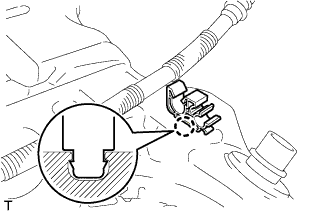
Engage the 2 claws and install the No. 1 evaporation vent tube clamp.
-
-
INSTALL FUEL TANK VENT TUBE SUB-ASSEMBLY
-
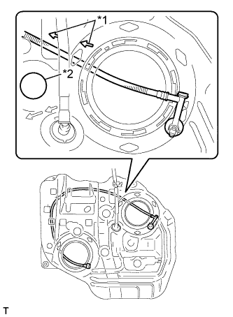
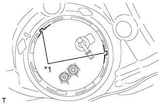
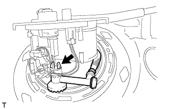
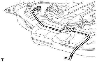
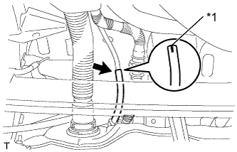
Text in Illustration *1 Arrows *2 Recession Insert the fuel tank vent tube from the sender gauge side, in the direction indicated by the arrows on the fuel tank, run the tube along the bottom edge of the fuel tank, and then pull it out on the fuel pump side.
Note
Do not run the fuel tank vent tube on the other side of the recession shown in the illustration.
-
-
INSTALL FUEL TANK SUCTION TUBE GASKET
-
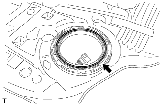
Install a new gasket to the fuel tank.
-
-
INSTALL FUEL SUCTION TUBE ASSEMBLY
-
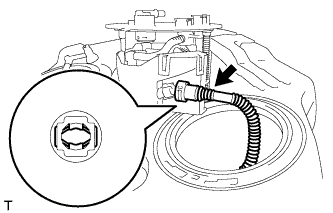
Line up the pipe and connector and push them together until a "click" sound is heard.
Note
-
Check that there are no scratches or foreign objects on the connecting part.
-
After connecting the pipe and connector, check that the pipe and connector are securely connected by pulling on them.
-
-
Install the fuel suction tube assembly to the fuel tank.
-
-
INSTALL FUEL PUMP GAUGE RETAINER
-
Text in Illustration *1 Cutout Align the protrusion of the fuel suction tube assembly with the cutouts of the fuel tank.
Note
Ensure that the fuel suction tube gasket is in the correct position.
-
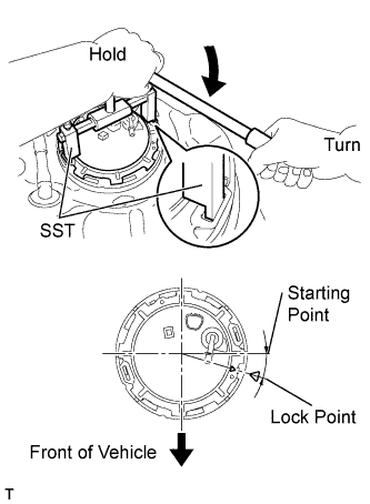
While holding the fuel suction tube assembly by hand, position the fuel pump gauge retainer and tighten it lightly by hand.
Note
Check that the contact surface of the fuel tank retainer is not scratched or damaged and prevent the entry of foreign objects.
-
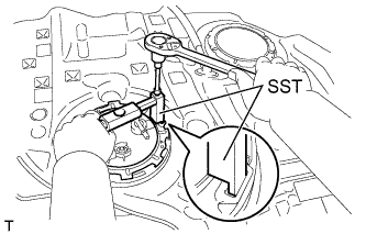
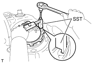
Using a 6 mm socket hexagon wrench, set SST to the fuel pump gauge retainer.
- SST
- 09808-14020 ( 09808-01410, 09808-01420, 09808-01430 )
Note
Do not use any tools other than SST.
Tech Tips
-
Hold the fuel suction tube assembly upright by hand to ensure that the fuel suction tube gasket is not moved out of position.
-
Align the ribs of the fuel pump gauge retainer with the tips of SST.
-
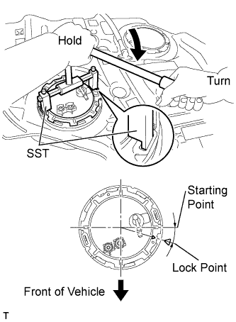
Using SST, align the marks on the fuel tank and fuel pump gauge retainer.
- SST
- 09808-14020 ( 09808-01410, 09808-01420, 09808-01430 )
-
-
INSTALL FUEL TANK SUCTION TUBE GASKET
-
Install a new gasket to the fuel tank.
-
-
INSTALL FUEL TANK VENT TUBE ASSEMBLY
-
Engage the 2 claws and connect the fuel tank vent tube sub-assembly to the fuel tank vent tube assembly.
-
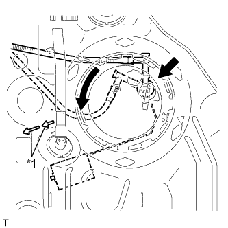
Text in Illustration *1 Arrows Rotate the fuel tank vent tube in the direction shown by the arrows, insert the sender gauge in the direction of the fuel tank gauge shown by the arrows, and then install the fuel tank vent tube assembly into the fuel tank.
Note
Do not bend the sender gauge arm.
-
-
INSTALL FUEL PUMP GAUGE RETAINER
-
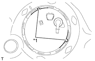
Text in Illustration *1 Cutout Align the protrusion of the fuel tank vent tube assembly with the cutouts of the fuel tank.
Note
Ensure that the fuel suction tube gasket is in the correct position.
-
While holding the fuel tank vent tube assembly by hand, position the fuel pump gauge retainer and tighten it lightly by hand.
Note
Check that the contact surface of the fuel tank retainer is not scratched or damaged and prevent the entry of foreign objects.
-
Using a 6 mm socket hexagon wrench, set SST to the fuel pump gauge retainer.
- SST
- 09808-14020 ( 09808-01410, 09808-01420, 09808-01430 )
Note
Do not use any tools other than SST.
Tech Tips
-
Hold the fuel tank vent tube assembly upright by hand to ensure that the fuel suction tube gasket is not moved out of position.
-
Align the ribs of the fuel pump gauge retainer with the tips of SST.
-
Using SST, align the marks on the fuel tank and fuel pump gauge retainer.
- SST
- 09808-14020 ( 09808-01410, 09808-01420, 09808-01430 )
-
-
INSTALL NO. 1 FUEL EVAPORATION TUBE SUB-ASSEMBLY
-
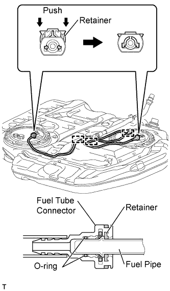
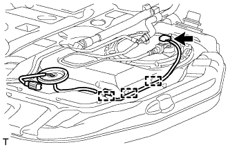
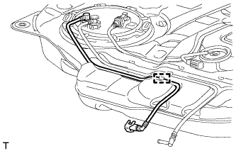
Connect the No. 1 fuel evaporation tube to the fuel suction tube and fuel tank vent tube assemblies and lock them by pushing in the retainers.
Note
-
Check that there are no scratches or foreign objects on the connecting part.
-
Check that the No. 1 fuel evaporation tube is inserted securely.
-
After installing the retainer, check that the No. 1 fuel evaporation tube is securely connected by pulling on it.
-
-
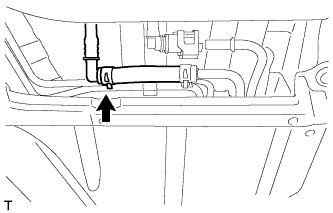
Engage the 3 clamps and install the No. 1 fuel evaporation tube to the fuel tank.
-
-
INSTALL NO. 1 CHARCOAL CANISTER OUTLET HOSE
-
Text in Illustration *1 Yellow mark Install the No. 1 charcoal canister outlet hose onto the fuel tank vent tube assembly.
Note
Install the No. 1 charcoal canister outlet hose with its yellow mark toward the rear of the vehicle.
-
Clamp the No. 1 charcoal canister outlet hose.
-
-
INSTALL FUEL TANK WIRE
-
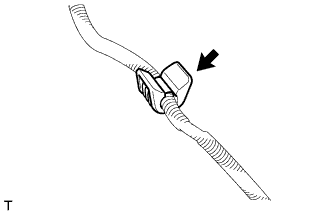
Install the fuel hose clamp to the fuel tank wire.
-
Connect the fuel tank wire connector to the fuel tank vent tube assembly.
-
Engage the 3 clamps and install the fuel tank wire to the fuel tank.
Tech Tips
After connecting the fuel tank wire connector, check that the fuel tank wire is inserted securely.
-
-
INSTALL FUEL RETURN TUBE SUB-ASSEMBLY
-
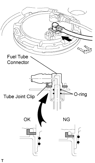
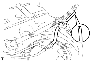
Insert the fuel tank return tube into the fuel suction tube assembly plug and secure it with the tube joint clip.
Note
-
Check that there are no scratches or foreign objects on the connecting part.
-
Check that the fuel return tube is inserted securely.
-
Check that the tube joint clip is on the collar of the fuel return tube.
-
After installing the tube joint clip, check that the fuel tank return tube is securely connected by pulling on it.
-
-
Engage the clamp and install the fuel tank return tube to the fuel tank.
-
-
INSTALL FUEL TANK MAIN TUBE SUB-ASSEMBLY
-
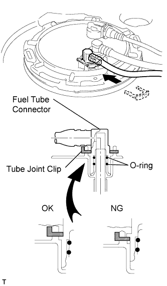
Insert the fuel tank main tube into the fuel suction tube assembly plug and secure it with the tube joint clip.
Note
-
Check that there are no scratches or foreign objects on the connecting part.
-
Check that the fuel tank main tube is inserted securely.
-
Check that the tube joint clip is on the collar of the fuel tank main tube.
-
After installing the tube joint clip, check that the fuel tank main tube is securely connected by pulling on it.
-
-
Engage the clamp and install the fuel tank main tube to the fuel tank.
-
-
INSTALL FUEL TANK CUSHION
-
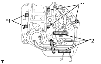
Text in Illustration *1 No. 1 fuel tank cushion *2 No. 2 fuel tank cushion Install the No. 1 fuel tank cushions and the No. 2 fuel tank cushions at the locations indicated in the illustration.
-
-
INSTALL FUEL TANK ASSEMBLY
-
Clean and degrease the bolt holes.
-
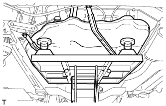
Set the fuel tank on the engine lifter.
-
Slowly raise the engine lifter and install the fuel tank onto the vehicle.
Note
Make sure that the fuel tank does not fall.
-
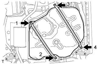
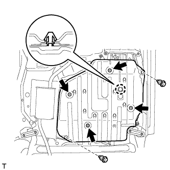
Tighten the 4 bolts in the sequence shown in the illustration, and secure the 2 fuel tank bands and the fuel tank.
- Torque:
- 39 N*m { 400 kgf*cm, 29 ft.*lbf }
-
-
CONNECT FUEL RETURN TUBE SUB-ASSEMBLY
-
Connect the fuel return tube sub-assembly.
-
-
CONNECT FUEL TANK MAIN TUBE SUB-ASSEMBLY
-
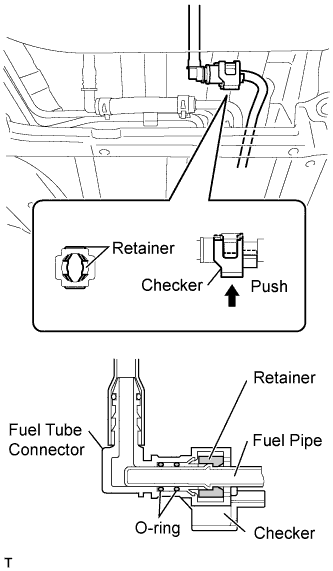
Line up the pipe and connector and push them together until a "click" sound is heard.
-
Push the checker into lock it.
Note
-
Check that there are no scratches or foreign objects on the connecting part.
-
Check that the fuel tank main tube is inserted securely.
-
After installing the checker, check that the fuel tank main tube is securely connected by pulling on it.
-
-
-
CONNECT FUEL TANK FILLER PIPE SUB-ASSEMBLY
-
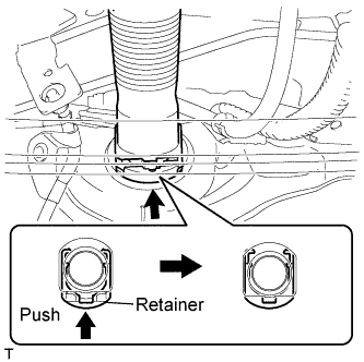
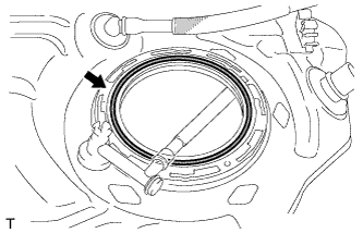
Connect the inlet tube to the fuel tank assembly and lock it by pushing in the retainer.
Note
-
Check that there are no scratches or foreign objects on the connecting part.
-
Check that the inlet tube is inserted securely.
-
After installing the retainer, check that the inlet tube is securely connected by pulling on it.
Tech Tips
-
Insert the inlet tube until a "click" sound is heard.
-
The quick connector cannot be locked when the tube is not inserted securely.
-
-
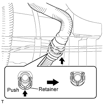
Connect the fuel tank breather tube to the fuel tank assembly and lock it by pushing in the retainer.
Note
-
Check that there are no scratches or foreign objects on the connecting part.
-
Check that the breather tube is inserted securely.
-
After installing the retainer, check that the breather tube is securely connected by pulling on it.
Tech Tips
The quick connector cannot be locked when the tube is not inserted securely.
-
-
-
CONNECT NO. 1 CHARCOAL CANISTER OUTLET HOSE
-
Text in Illustration *1 Yellow mark Connect the No. 1 charcoal canister outlet hose.
Note
-
Install the No. 1 charcoal canister outlet hose with its yellow mark toward the rear of the vehicle.
-
After connecting the fuel tank breather tube and No. 1 charcoal canister outlet hose, check that the evaporation vent tube clamp is securely connected by pulling on it.
-
-
-
INSTALL NO. 1 FUEL TANK PROTECTOR SUB-ASSEMBLY
-
Engage the claw and install the No. 1 fuel tank protector with the 2 clips and 4 nuts.
- Torque:
- 5.5 N*m { 56 kgf*cm, 49 in.*lbf }
-
-
CONNECT FUEL TANK WIRE
-
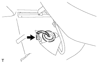
Pull the fuel tank wire through the floor, install the grommet in the floor, and connect the fuel tank wire connector.
-
-
ADD FUEL
-
Open the fuel tank cap to add fuel.
-
-
BLEED AIR FROM FUEL SYSTEM
-
INSPECT FOR FUEL LEAK
-
Connect an intelligent tester to the DLC3.
-
Turn the ignition switch to ON.
-
Turn the tester on.
-
Enter the following menus: Powertrain / Engine / Active Test.
-
Perform the Active Test.
Intelligent Tester Display Test Details Control Range Diagnostic Notes Test the Fuel Leak Pressurize common rail internal fuel pressure, and check for fuel leaks Stop/Start Perform inspection of the high pressure fuel system.
Test is possible when the following conditions are met:
-
Warmed up engine.
-
Vehicle is stopped.
-
Battery voltage is 12 V or more.
-
PM regeneration is not operating.
-
Engine speed is less than 4000 rpm.
Results of real-vehicle check:
-
Engine Speed: 2702 rpm
-
Fuel Pressure: 108570 kPa
-
Target Common Rail Pressure: 105500 kPa
-
Target Pump SCV Current: 1.2 A
-
MAP: 127 kPa
-
MAF: 28 g/sec.
-
-