FUEL SUPPLY PUMP INSTALLATION

-
INSTALL SUPPLY PUMP DRIVE COUPLING
-
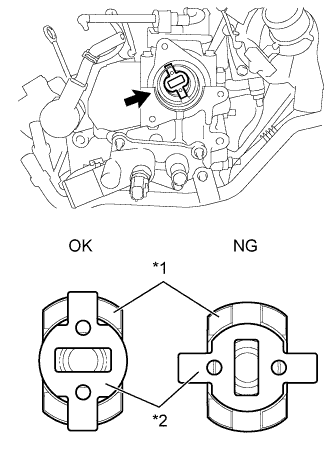
Text in Illustration *1 Camshaft *2 Supply Pump Drive Coupling Install the supply pump drive coupling into the camshaft.
Note
Install the supply pump drive coupling in the correct direction.
-
-
INSTALL SUPPLY PUMP ASSEMBLY
Note
When installing, clean the seal surfaces of the fuel inlet pipe, supply pump and common rail.
-
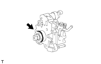
Apply a light coat of engine oil to a new O-ring.
-
Install the O-ring onto the supply pump.
-
Temporarily install the supply pump with the 3 bolts.
-
Remove the plastic bag and rubber band from the supply pump.
-
-
INSTALL FUEL INLET PIPE SUB-ASSEMBLY
Note
-
When replacing the supply pump, the fuel inlet pipe must also be replaced.
-
Replace the fuel inlet pipe with a new one when the fuel inlet pipe has been removed and reinstalled more than 5 times.
-
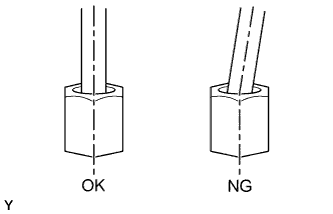
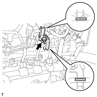
Temporarily install the fuel inlet pipe onto the supply pump and common rail.
Note
Install the pipe and union nut vertically, not at a tilt.
-
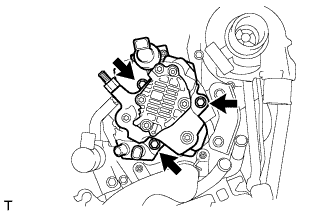
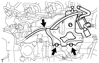
Tighten the supply pump with the 3 bolts.
- Torque:
- 21 N*m { 214 kgf*cm, 15 ft.*lbf }
-
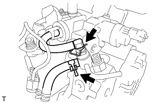
Using a union nut wrench (17 mm), tighten the fuel inlet pipe union nut on the common rail side.
- Torque:
- 28 N*m { 286 kgf*cm, 20 ft.*lbf }
Note
Use the formula to calculate special torque values for situations where a union nut wrench is combined with a torque wrench Click here.
-
Using a wrench (17 mm), hold the supply pump nut, using a union nut wrench (17 mm), tighten the fuel inlet pipe union nut on the supply pump side.
- Torque:
- 28 N*m { 286 kgf*cm, 20 ft.*lbf }
Note
Use the formula to calculate special torque values for situations where a union nut wrench is combined with a torque wrench Click here.
-
Connect the No. 2 fuel hose.
-
Connect the nozzle leakage pipe and install a new retainer spring onto the supply pump.
-
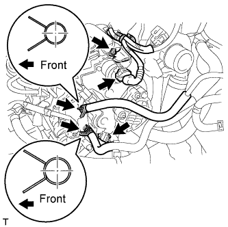
Connect the 2 connectors.
-
Connect the harness bracket with bolt.
- Torque:
- 8.0 N*m { 82 kgf*cm, 71 in.*lbf }
-
Connect the 2 fuel hoses.
-
-
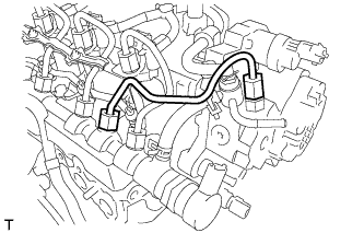
INSTALL NO. 2 INJECTION PIPE CLAMP
-
Install both sides of the No. 2 injection pipe clamp with the nut as shown in the illustration.
- Torque:
- 9.0 N*m { 92 kgf*cm, 80 in.*lbf }
-
-
INSTALL NO. 1 EGR COOLER BRACKET
-
Install the No. 1 EGR cooler bracket with the 2 bolts.
- Torque:
- 23 N*m { 235 kgf*cm, 17 ft.*lbf }
-
Connect the vacuum hose.
-
-
INSTALL EGR WITH COOLER PIPE ASSEMBLY
-
Install the EGR with cooler pipe assembly Click here.
-
-
BLEED AIR FROM FUEL SYSTEM
-
INSPECT FOR FUEL LEAK
-
Connect an intelligent tester to the DLC3.
-
Turn the ignition switch to ON.
-
Turn the tester on.
-
Enter the following menus: Powertrain / Engine / Active Test.
-
Perform the Active Test.
Intelligent Tester Display Test Details Control Range Diagnostic Notes Test the Fuel Leak Pressurize common rail internal fuel pressure, and check for fuel leaks Stop/Start Perform inspection of the high pressure fuel system.
Test is possible when the following conditions are met:
-
Warmed up engine.
-
Vehicle is stopped.
-
Battery voltage is 12 V or more.
-
PM regeneration is not operating.
-
Engine speed is less than 4000 rpm.
Results of real-vehicle check:
-
Engine Speed: 2702 rpm
-
Fuel Pressure: 108570 kPa
-
Target Common Rail Pressure: 105500 kPa
-
Target Pump SCV Current: 1.2 A
-
MAP: 127 kPa
-
MAF: 28 g/sec.
-
-