FUEL INJECTOR INSTALLATION

-
INSTALL INJECTION NOZZLE SEAT
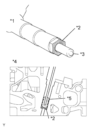
Text in Illustration *1 Injector *2 Sealing Surface *3 Nozzle *4 Cylinder Head *5 Cloth Note
-
When installing, clean the sealing surface of the injector, injection pipe and common rail.
-
When replacing the injectors, the injection pipes must also be replaced.
-
Replace the injection pipe with a new one when the injection pipe has been removed and reinstalled more than 5 times.
-
Replace the injector with one with the same part number and install it onto the cylinder.
-
Using a cloth and solvent, wipe away any carbon from the sealing surface of the injector and injector installation hole, as shown in the illustration.
Note
-
Do not damage the sealing surface.
-
Do not touch the injector nozzle.
-
-
Install 4 new nozzle seats onto the cylinder head.
-
-
INSTALL INJECTOR ASSEMBLY
-
Install the 4 injectors onto the cylinder head.
Tech Tips
Fit the injectors into the seats.
-
-
INSTALL NOZZLE HOLDER CLAMP SEAT
-
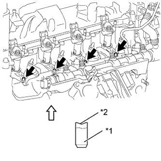
Text in Illustration *1 Nozzle holder clamp seat *2 Concave 
Upper Direction Install the 4 nozzle holder clamp seats onto the cylinder head.
Note
Install the nozzle holder clamp seats with the concave end facing up.
-
-
INSTALL NO. 1 NOZZLE HOLDER CLAMP
-
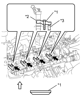
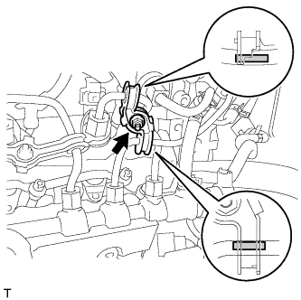
Text in Illustration *1 Washer *2 Nozzle holder clamp *3 Nozzle holder clamp seat Upper Direction Install the 4 nozzle holder clamps onto the injectors.
-
Set the washer on the nozzle holder clamp, as shown illustration.
Note
Install the washer in the correct direction.
-
Tighten the 4 nozzle holder clamp bolts.
- Torque:
- 19 N*m { 194 kgf*cm, 14 ft.*lbf }
-
-
INSTALL NOZZLE LEAKAGE PIPE ASSEMBLY
-
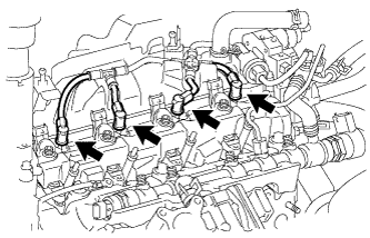
Install the nozzle leakage pipe into each injector.
-
Make sure the lock bush is at the top position.
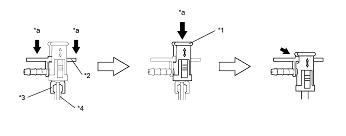
Text in Illustration *1 Lock Bush *2 Return Plug *3 Lest Arm *4 Injector *a Push - - -
Insert the rest arm into the injector and push both sides of the return plug until the rest arm engages with the injector, as shown in the illustration.
Tech Tips
Push the nozzle leakage pipe until it makes a click sound.
-
Push the lock bush until it fits with the return plug, as shown in the illustration.
-
-
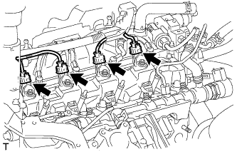
Connect the 4 injector connectors.
-
-
INSTALL NO. 2 INTAKE MANIFOLD INSULATOR
-
Install the No. 2 intake manifold insulator.
-
-
INSTALL NO. 1 GLOW PLUG CONNECTOR
-

Install the No. 1 glow plug connector with the 4 nuts.
- Torque:
- 2.2 N*m { 22 kgf*cm, 19 in.*lbf }
-
Connect the glow terminal with the nut.
- Torque:
- 4.0 N*m { 41 kgf*cm, 35 in.*lbf }
Tech Tips
Install the glow terminal in the correct direction.
-
Install the 5 screw grommets.
Tech Tips
Push the screw grommet into the threaded portion of the glow plug by hand, and then turn it clockwise.
-
-
INSTALL NO. 1 INJECTION PIPE SUB-ASSEMBLY
-
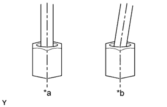
Text in Illustration *a Correct *b Incorrect Temporarily install 4 new injection pipes onto the injectors and common rail.
Note
Install the pipe and union nut vertically, not at a tilt.
-
Using a union nut wrench (17 mm), tighten the injection pipe union nut on the common rail, and then tighten the union nut on the injector.
- Torque:
- 28 N*m { 286 kgf*cm, 20 ft.*lbf }
Note
Use the formula to calculate special torque values for situations where a union nut wrench is combined with a torque wrench Click here.
-
-
INSTALL NO. 2 INJECTION PIPE SUB-ASSEMBLY
Tech Tips
Perform the same procedure as for injection pipe No. 1.
-
INSTALL NO. 3 INJECTION PIPE SUB-ASSEMBLY
Tech Tips
Perform the same procedure as for injection pipe No. 1.
-
INSTALL NO. 1 INJECTION PIPE CLAMP
-
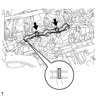
Install both sides of the No. 1 injection pipe clamp with the 2 nuts as shown in the illustration.
- Torque:
- 9.0 N*m { 92 kgf*cm, 80 in.*lbf }
-
-
INSTALL NO. 2 INJECTION PIPE CLAMP
-
Install both sides of the No. 2 injection pipe clamp with the nut as shown in the illustration.
- Torque:
- 9.0 N*m { 92 kgf*cm, 80 in.*lbf }
-
-
INSTALL NO. 1 EGR COOLER BRACKET
-
Install the No. 1 EGR cooler bracket with the 2 bolts.
- Torque:
- 23 N*m { 235 kgf*cm, 17 ft.*lbf }
-
Connect the vacuum hose.
-
-
INSTALL EGR WITH COOLER PIPE ASSEMBLY
-
PERFORM REGISTRATION AND INITIALIZATION
-
BLEED AIR FROM FUEL SYSTEM
-
INSPECT FOR FUEL LEAK
-
Connect an intelligent tester to the DLC3.
-
Turn the ignition switch to ON.
-
Turn the tester on.
-
Enter the following menus: Powertrain / Engine / Active Test.
-
Perform the Active Test.
Intelligent Tester Display Test Details Control Range Diagnostic Notes Test the Fuel Leak Pressurize common rail internal fuel pressure, and check for fuel leaks Stop/Start Perform inspection of the high pressure fuel system.
Test is possible when the following conditions are met:
-
Warmed up engine.
-
Vehicle is stopped.
-
Battery voltage is 12 V or more.
-
PM regeneration is not operating.
-
Engine speed is less than 4000 rpm.
Results of real-vehicle check:
-
Engine Speed: 2702 rpm
-
Fuel Pressure: 108570 kPa
-
Target Common Rail Pressure: 105500 kPa
-
Target Pump SCV Current: 1.2 A
-
MAP: 127 kPa
-
MAF: 28 g/sec.
-
-