FUEL SENDER GAUGE ASSEMBLY INSPECTION

-
INSPECT FUEL SENDER GAUGE ASSEMBLY
-
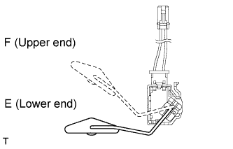
Text in Illustration *a F (Upper end) *b E (Lower end) Check the fuel sender gauge operation.
-
Check that the float moves smoothly between the F level (upper end) and E level (lower end).
OK The float moves smoothly.
-
-
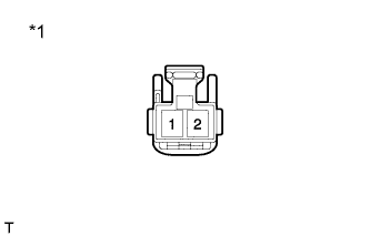
Text in Illustration *a Component without harness connected
(Fuel sender gauge)
Check the fuel sender gauge resistance.
-
Measure the resistance according to the value(s) in the table below.
Standard Resistance Tester Connection Condition Specified Condition 1 - 2 F (Upper End) 161 to 178.5 Ω 1 - 2 E (Lower End) 386 to 415 Ω 1 - 2 F (Upper End) - E (Lower End) The resistance changes smoothly If the result is not as specified, replace the fuel sender gauge assembly.
-
-