ENGINE UNIT INSTALLATION

-
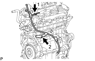
INSTALL WIRING HARNESS CLAMP BRACKET
-
Install the wiring harness clamp bracket to the cylinder head cover with the bolt.
- Torque:
- 10 N*m { 102 kgf*cm, 7 ft.*lbf }
-
Install the wiring harness clamp bracket to the cylinder head with the bolt.
- Torque:
- 8.0 N*m { 82 kgf*cm, 71 in.*lbf }
-
Install the wiring harness clamp bracket to the cylinder block with the bolt.
- Torque:
- 21 N*m { 214 kgf*cm, 15 ft.*lbf }
-
-
INSTALL V-RIBBED BELT TENSIONER ASSEMBLY
-
Install the V-ribbed belt tensioner with the 2 bolts.
- Torque:
- 21 N*m { 214 kgf*cm, 15 ft.*lbf }
-
-
INSTALL V-RIBBED BELT TENSIONER ASSEMBLY (w/ No. 1 Engine Cover)
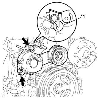
*1 Stopper
-
Install the V-ribbed belt tensioner and engine cover bracket with the 2 bolts.
Note
Attach stopper of the bracket to the auto tensioner.
- Torque:
- 21 N*m { 214 kgf*cm, 15 ft.*lbf }
-
-
INSTALL NO. 2 IDLE PULLEY ASSEMBLY (w/ Air Conditioning System)
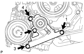
-
Temporarily install the No. 2 idle pulley with the 4 bolts.
-
Fully tighten the 4 bolts in the order shown in the illustration.
- Torque:
- 25 N*m { 250 kgf*cm, 18 ft.*lbf }
-
-
INSTALL NO. 1 WATER BY-PASS PIPE
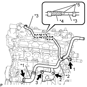
Text in Illustration *1 Water By-Pass Hose *2 No. 1 water by-pass pipe *3 No. 2 Water By-Pass Hose *4 Protector *5 Clip
-
Connect the water by-pass hose to the water inlet with the clip.
Note
Install the clip so that its claws face away from the engine.
-
Temporarily install the No. 1 water by-pass pipe with the 3 bolts.
-
Fully tighten the 3 bolts in the order shown in the illustration.
- Torque:
- 22 N*m { 224 kgf*cm, 16 ft.*lbf }
-
Engage the No. 2 water by-pass hose to the 3 clamps as shown in the illustration.
-
-
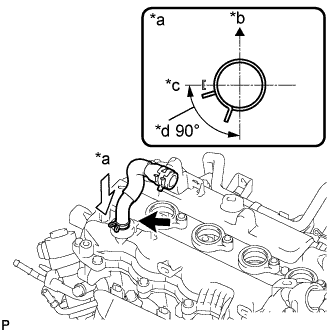
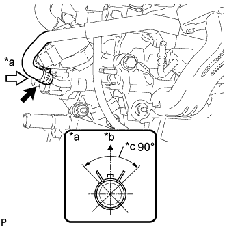
INSTALL NO. 2 VENTILATION HOSE
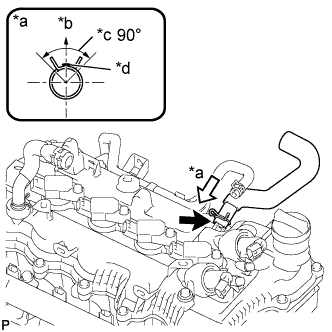
Text in Illustration *a View A *b Upper *c Clip center installation range *d Paint mark of the hose
-
Install the ventilation hose to the cylinder head with the clip.
Note
-
Install the clip so that its claws are within the clip center installation range.
-
The protrusion of the head cover should overlap the paint mark of the hose.
-
-
-
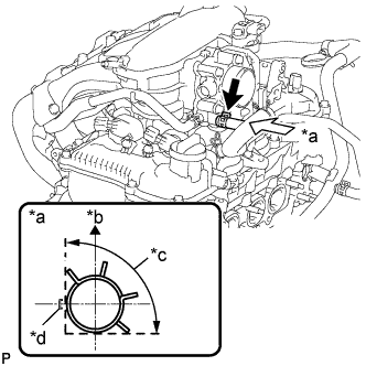
INSTALL VENTILATION HOSE
Text in Illustration *a View A *b Left *c Rear *d Clip center installation range
-
Install the ventilation hose to the cylinder head with the clip.
Note
Install the clip so that its claws are within the clip center installation range.
-
-
INSTALL NO. 1 IGNITION COIL
-
Install the 4 ignition coils with the 4 bolts.
- Torque:
- 10 N*m { 102 kgf*cm, 7 ft.*lbf }
-
-
INSTALL INJECTOR VIBRATION INSULATOR
-
Install 4 new injector vibration insulators onto the cylinder head.
-
-
INSTALL NO. 1 DELIVERY PIPE SPACER
-
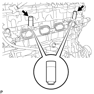
Install the 2 No. 1 delivery pipe spacers onto the cylinder head.
Note
Install the No. 1 delivery pipe spacers in the correct direction.
-
-
INSTALL FUEL INJECTOR ASSEMBLY
-
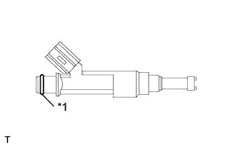
Text in Illustration *1 O-Ring Apply a light coat of gasoline or spindle oil to new O-rings, then install one onto each fuel injector assembly.
-
Apply a light coat of gasoline or spindle oil to the contact surfaces of the fuel delivery pipe and the O-ring of the fuel injector assembly.
-
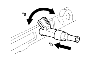
Text in Illustration *a Turn *b Push While turning the fuel injector assembly left and right, install it onto the fuel delivery pipe sub-assembly.
Note
-
Do not twist the O-ring.
-
After installing the fuel injectors, check that they turn smoothly. If not, replace the O-ring with a new one.
-
-
-
INSTALL FUEL DELIVERY PIPE
-
Install the fuel delivery pipe with the 4 fuel injectors, and then temporarily install the 2 bolts.
Note
-
Do not drop the fuel injectors when installing the fuel delivery pipe sub-assembly.
-
Check that the fuel injector assemblies rotate smoothly after installing the fuel delivery pipe sub-assembly.
-
-
Tighten the 2 bolts to the specified torque.
- Torque:
- 28 N*m { 286 kgf*cm, 21 ft.*lbf }
-
-
INSTALL EGR VALVE ASSEMBLY
-
Install a new EGR valve gaskets onto the cylinder head.
-
Install the EGR valve with the bolt and 2 new nuts.
- Torque:
- 28 N*m { 286 kgf*cm, 21 ft.*lbf }
-
-
INSTALL ENGINE OIL LEVEL DIPSTICK GUIDE
-
Install a new O-ring to the oil level dipstick guide.
Tech Tips
Apply engine oil to the O-ring and install the oil level dipstick guide into the oil pan.
-
Temporarily install the engine oil level dipstick guide with the 2 bolts.
-
Fully tighten the 2 bolts in the order shown in the illustration.
- Torque:
- 18 N*m { 184 kgf*cm, 13 ft.*lbf }
-
-
INSTALL ENGINE OIL LEVEL DIPSTICK
-
INSTALL NO. 4 ENGINE WIRE
-
Engage the 7 clamps and install the No. 4 engine wire.
-
Install the ground bolt.
- Torque:
- 8.4 N*m { 86 kgf*cm, 74 in.*lbf }
-
Connect the 4 fuel injector connectors.
-
Connect the 4 ignition coil connectors.
-
Connect the 2 camshaft timing oil control valve connectors.
-
-
INSTALL INTAKE MANIFOLD ASSEMBLY
-
Install a new No. 2 intake manifold to head gasket onto the cylinder head.
-
Install the EGR delivery chamber onto the No. 2 intake manifold to head gasket.
-
Install a new intake manifold to head gasket onto the EGR delivery chamber.
-
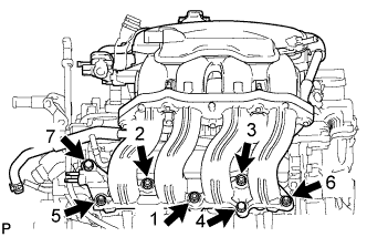
Temporarily install the intake manifold with the 5 bolts and 2 nuts.
-
Fully tighten the 5 bolts and 2 nuts in the order shown in the illustration.
- Torque:
- 28 N*m { 286 kgf*cm, 21 ft.*lbf }
-
-
INSTALL EGR PIPE CONNECTOR
-
Install 2 new EGR pipe gaskets onto the intake manifold and the EGR valve.
-
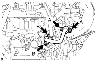
Temporarily install the EGR pipe connector with the 4 nuts.
-
Fully tighten the A nuts first, and then tighten nut B.
- Torque:
- 10 N*m { 102 kgf*cm, 7 ft.*lbf }
-
-
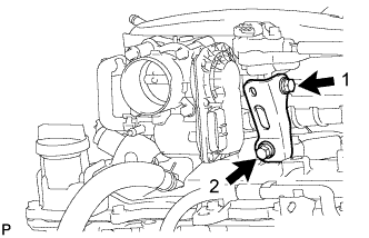
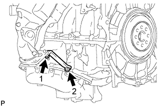
INSTALL INTAKE MANIFOLD STAY
-
Temporarily install the intake manifold stay with the 2 bolts.
-
Fully tighten the 2 bolts in the order shown in the illustration.
- Torque:
- 28 N*m { 286 kgf*cm, 21 ft.*lbf }
-
-
CONNECT NO. 4 WATER BY-PASS HOSE
Text in Illustration *a View A *b Upper *c Clip center installation range
-
Connect the No. 4 water by-pass hose to the EGR valve with the clip.
Note
Install the clip so that its claws are within the clip center installation range.
-
-
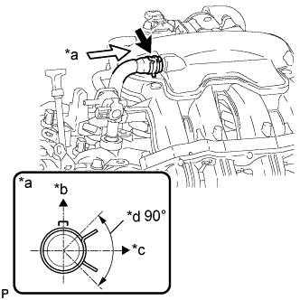
CONNECT NO. 2 WATER BY-PASS HOSE
Text in Illustration *a View A *b Upper *c Clip installation range *d Paint mark of the hose
-
Connect the No. 2 water by-pass hose to the throttle body with the clip.
Note
-
Install the clip so that its claws are within the clip installation range.
-
Line up the rib of the throttle with motor body assembly with the center of the paint mark.
-
-
-
CONNECT VENTILATION HOSE
Text in Illustration *a View A *b Upper *c Left *d Clip center installation range
-
Connect the ventilation hose to the intake manifold with the clip.
Note
Install the clip so that its claws are within the clip center installation range.
-
-
INSTALL EXHAUST MANIFOLD CONVERTER SUB-ASSEMBLY
-
Install the new exhaust manifold to head gasket and the new inlet EGR gasket onto the cylinder head.
-
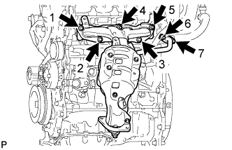
Temporarily install the exhaust manifold converter with the 3 bolts and 4 nuts.
-
Fully tighten the 3 bolts and 4 nuts in the order shown in the illustration.
- Torque:
- 28 N*m { 286 kgf*cm, 21 ft.*lbf }
-
-
INSTALL MANIFOLD STAY
-
Temporarily install the manifold stay with the bolt and nut.
-
Fully tighten the bolt and nut in the order shown in the illustration.
- Torque:
- 28 N*m { 286 kgf*cm, 21 ft.*lbf }
-
-
INSTALL NO. 1 EXHAUST MANIFOLD HEAT INSULATOR
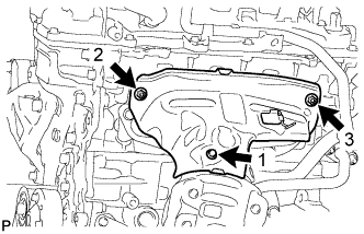
-
Temporarily install the exhaust manifold heat insulator with the bolt and 2 nuts.
-
Fully tighten the bolt and 2 nuts in the order shown in the illustration.
- Torque:
- 10 N*m { 102 kgf*cm, 7 ft.*lbf }
-
-
INSTALL GENERATOR ASSEMBLY
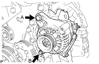
-
Install the generator with the 2 bolts.
- Torque:
- Bolt A
- 54 N*m { 551 kgf*cm, 40 ft.*lbf }
- Bolt B
- 21 N*m { 214 kgf*cm, 15 ft.*lbf }
-