ENGINE UNIT DISASSEMBLY

-
REMOVE REAR ENGINE OIL SEAL (w/o Stop and Start System)
-
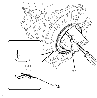
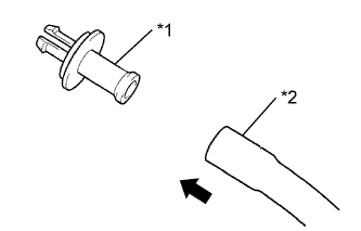
Text in Illustration *1 Protective Tape *a Cut Position Using a knife, cut off the oil seal lip.
-
Using a screwdriver with its tip wrapped with protective tape, pry out the rear engine oil seal.
-
-
REMOVE REAR ENGINE OIL SEAL (w/ Stop and Start System)
-
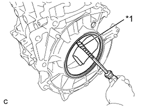
Text in Illustration *1 Protective Tape Using a screwdriver with its tip wrapped with protective tape, pry out the rear engine oil seal.
Note
-
If the snap ring is broken, the ring gear may move out from its original position and result in an oil leak. Therefore, it is necessary to confirm that the snap ring is installed correctly and undamaged when replacing the oil seal.
-
Be careful not to damage the crankshaft bearing.
-
-
-
REMOVE CRANKSHAFT BEARING (w/ Stop and Start System)
-
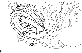
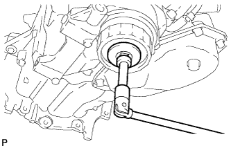
Using SST, hold the crankshaft.
- SST
- 09960-10010 ( 09962-01000, 09963-01000 )
-
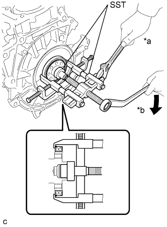
Text in Illustration *a Hold *b Turn Using SST, remove the crankshaft bearing from the crankshaft.
- SST
- 09950-40011 ( 09951-04010, 09952-04010, 09953-04020, 09954-04010, 09955-04071, 09957-04010, 09958-04011 )
- 09950-60010 ( 09951-00280, 09951-00380, 09952-06010 )
-
Remove the snap ring from the bearing.
-
-
REMOVE OIL FILLER CAP SUB-ASSEMBLY
-
Remove the oil filler cap.
-
-
REMOVE OIL FILLER CAP GASKET
-
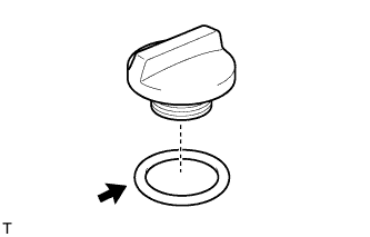
Remove the gasket from the oil filler cap.
-
-
REMOVE SPARK PLUG
Text in Illustration *1 14 mm Spark Plug Wrench
-
Using a 14 mm spark plug wrench, remove the 4 spark plugs.
-
-
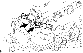
REMOVE CAMSHAFT TIMING OIL CONTROL VALVE ASSEMBLY
-
Remove the 2 bolts, 2 O-rings and the 2 camshaft timing oil control valves.
-
-
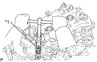
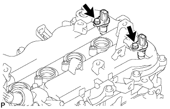
REMOVE NO. 1 CRANKSHAFT POSITION SENSOR
-
Remove the 2 bolts and the 2 No. 1 crankshaft position sensors.
-
-
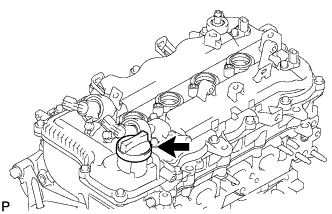
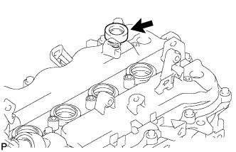
REMOVE VENTILATION VALVE SUB-ASSEMBLY
-
Remove the ventilation valve.
-
-
REMOVE VENTILATION SYSTEM GROMMET
-
Remove the ventilation system grommet from the cylinder head cover.
-
-
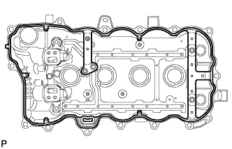
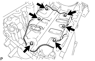
REMOVE CYLINDER HEAD COVER SUB-ASSEMBLY
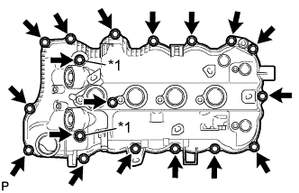
Text in Illustration *1 Seal Washer
-
Remove the 18 bolts, 2 seal washers and the cylinder head cover.
Note
Be careful not to drop any of the gaskets into the engine when removing the cylinder head cover because the gaskets may stick to the cylinder head cover.
-
Remove the cylinder head cover gasket.
-
-
REMOVE CAMSHAFT BEARING CAP OIL HOLE GASKET
-
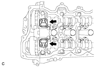
Remove the 2 camshaft bearing cap oil hole gaskets from the camshaft bearing cap.
-
-
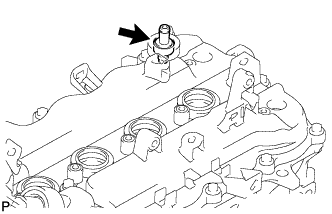
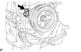
REMOVE CRANKSHAFT POSITION SENSOR
-
Remove the bolt and the crankshaft position sensor.
-
-
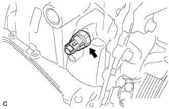
REMOVE ENGINE OIL PRESSURE SWITCH ASSEMBLY
-
Using a 24 mm deep socket wrench, remove the engine oil pressure switch.
-
-
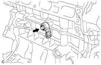
REMOVE KNOCK SENSOR
-
Remove the bolt and sensor.
-
-
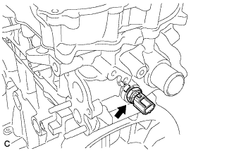
REMOVE ENGINE COOLANT TEMPERATURE SENSOR
-
Using a 19 mm deep socket wrench, remove the engine coolant temperature sensor.
-
Remove the gasket from the engine coolant temperature sensor.
-
-
REMOVE OIL FILTER ELEMENT
-
Text in Illustration *1 Pipe *2 Hose Connect a hose with an inside diameter of 15 mm (0.591 in.) to the pipe.
-
Remove the oil filter drain plug.
-
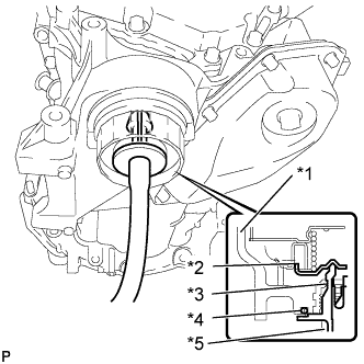
Text in Illustration *1 Cap *2 Valve *3 Pipe *4 O-ring *5 Hose Install the pipe to the oil filter cap.
Note
If the O-ring is removed with the drain plug, install the O-ring together with the pipe.
Tech Tips
Use a container to catch the draining oil.
-
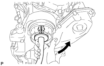
Check that oil is drained from the oil filter. Then disconnect the pipe as shown in the illustration.
-
Remove the O-ring.
-
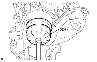
Using SST, remove the oil filter cap.
- SST
- 09228-06501
-

Text in Illustration *1 O-ring *2 Oil Filter Element Remove the oil filter element and O-ring from the oil filter cap.
Note
Be sure to remove the O-ring (for the cap) by hand, without using any tools, to prevent damage to the groove.
-
-
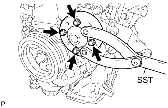
REMOVE WATER PUMP PULLEY
-
Using SST, remove the 4 bolts and water pump pulley.
- SST
- 09960-10010 ( 09962-01000, 09963-00600 )
-
-
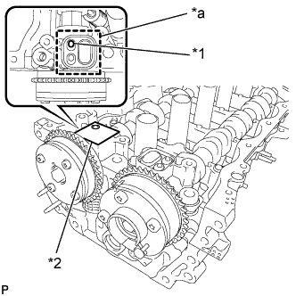
SET NO. 1 CYLINDER TO TDC/COMPRESSION
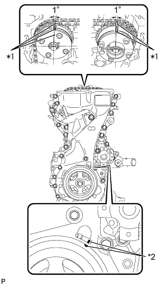
Text in Illustration *1 Timing Mark *2 Groove
-
Turn the crankshaft pulley until its groove and the groove of the timing chain cover are aligned.
-
Check that each timing mark of the camshaft timing gear and sprocket are located as shown in the illustration. If not, turn the crankshaft 1 revolution (360°) to align the timing marks as shown in the illustration.
-
-
REMOVE CRANKSHAFT PULLEY
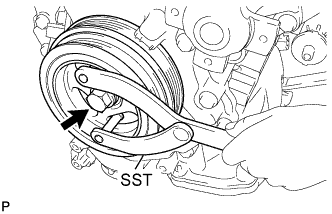
-
Using SST, remove the crankshaft pulley bolt.
- SST
- 09960-10010 ( 09962-01000, 09963-01000 )
-
Remove the crankshaft pulley from the crankshaft.
-
-
REMOVE TIMING CHAIN COVER SUB-ASSEMBLY
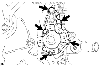
-
Remove the 5 bolts and the water pump, water pump gasket from the timing chain cover.
-
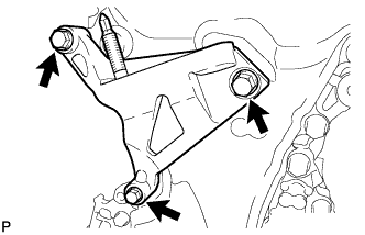
Remove the 3 bolts and the engine mounting bracket.
-
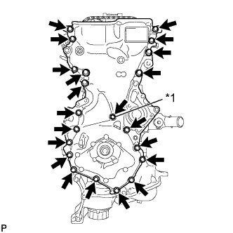
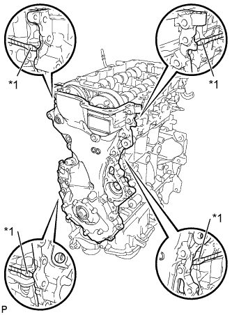
Text in Illustration *1 Seal Washer Remove the 21 bolts and seal washer.
-
Text in Illustration *1 Protective Tape Using a screwdriver with its tip wrapped with protective tape, remove the timing chain cover by prying between the timing chain cover and cylinder head or cylinder block.
Note
Be careful not to damage the contact surfaces of the timing chain cover, cylinder block, and cylinder head.
-
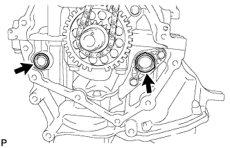
Remove the 2 O-rings.
-
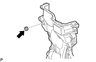
Using an 8 mm socket hexagon wrench, remove the plug.
-
-
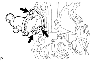
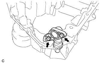
REMOVE WATER INLET
-
Remove the 3 bolts and the water inlet.
-
-
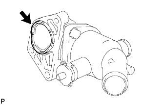
REMOVE NO. 2 WATER INLET HOUSING GASKET
-
Remove the No. 2 water inlet housing gasket from the water inlet.
-
-
REMOVE TIMING CHAIN COVER OIL SEAL
-
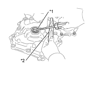
Text in Illustration *1 Protective Tape *2 Wooden Block Using a screwdriver with its tip wrapped with protective tape, remove the timing chain cover oil seal.
Note
Do not damage the surface of the oil seal press fit hole.
-
-
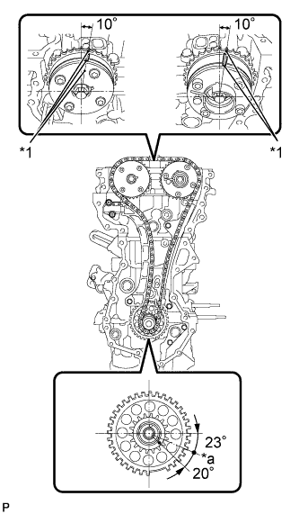
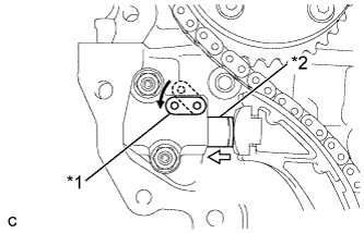
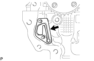
REMOVE NO. 1 CHAIN TENSIONER ASSEMBLY
-
Set the camshaft timing gear, camshaft timing exhaust gear and crankshaft in the positions (20° ATDC) shown in the illustration.
Text in Illustration *1 Timing Mark *a TDC -
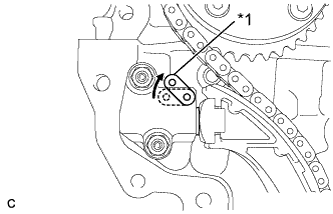
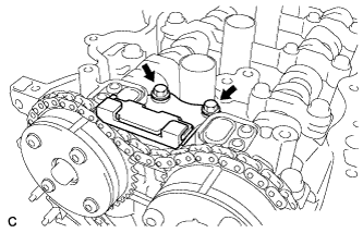
Text in Illustration *1 Stopper Plate *2 Plunger 
Push Push down on the stopper plate to release the lock and push in the plunger.
-
Text in Illustration *1 Stopper Plate Pull up the stopper plate with the plunger pushed to the end and lock the plunger.
-
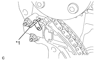
Text in Illustration *1 Bar Insert a 3 mm (0.118 in.) diameter bar into the hole in the stopper plate and lock the plunger.
-
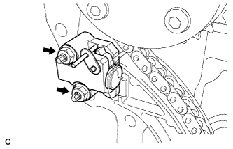
Remove the 2 nuts and the No. 1 chain tensioner.
-
Remove the gasket from the cylinder head.
-
-
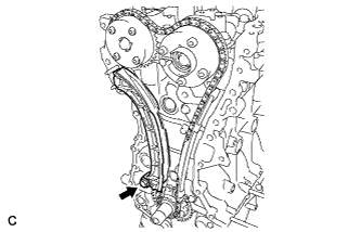
REMOVE NO. 2 CHAIN VIBRATION DAMPER
-
Remove the 2 bolts and the No. 2 chain vibration damper.
-
-
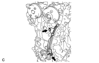
REMOVE TIMING CHAIN TENSION ARM
-
Remove the bolt and the timing chain tension arm.
-
-
REMOVE CHAIN SUB-ASSEMBLY
-
Remove the chain.
-
-
REMOVE TIMING CHAIN GUIDE
-
Remove the 2 bolts and the timing chain guide.
-
-
REMOVE CAMSHAFT TIMING GEAR ASSEMBLY
-
Check the lock of the camshaft timing gear.
-
Release the lock pin.
Note
Before removing the camshaft timing gear, make sure that the lock pin has been released.
-
After cleaning and degrease the VVT oil hole on the intake side of the No. 1 camshaft bearing cap, completely seal the oil hole with adhesive tape or equivalent as shown in the illustration to prevent air from leaking.
Note
Be sure to cover the oil hole completely because air leaks due to insufficient sealing will prevent the lock pin from being released.
-
Prick a hole in the tape covering the oil hole as shown in the illustration (Procedure A).
-
Text in Illustration *1 Prick a Hole *2 Adhesive Tape *a Adhesive Tape Sealing Area Apply approximately 150 kPa (1.5 kgf/cm2, 22 psi) of air pressure to the hole pricked in procedure A to release the lock pin.
Note
-
If air leaks out, reattach adhesive tape.
-
Cover the oil hole with a piece of cloth when applying air pressure to prevent oil from spraying.
-
Do not lock the camshaft timing gear. If it is locked, release the lock pin again.
Tech Tips
-
The camshaft timing gear may be turned in the advance direction without applying any force.
-
If enough air pressure cannot be applied because of air leakage from the port, releasing the lock pin may be difficult.
-
-
Remove the adhesive tape from the No. 1 camshaft bearing cap.
-
-
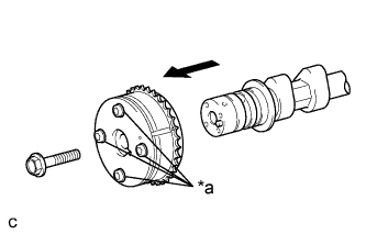
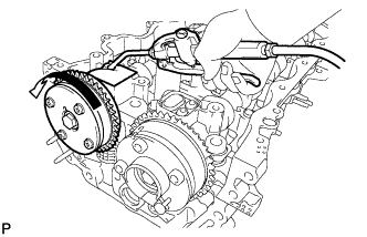
Text in Illustration *a Do Not Remove Remove the flange bolt while holding the hexagonal portion of the camshaft, and then remove the camshaft timing gear.
Note
-
Before removing the camshaft timing gear, make sure that the lock pin has been released.
-
Be sure not to remove the other 4 bolts.
-
Keep the camshaft timing gear horizontal while removing it from the camshaft.
-
-
-
REMOVE CAMSHAFT TIMING EXHAUST GEAR ASSEMBLY
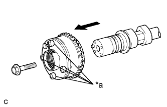
Text in Illustration *a Do Not Remove
-
Remove the flange bolt while holding the hexagonal portion of the camshaft, and then remove the camshaft timing exhaust gear.
Note
-
Be sure not to remove the other 4 bolts.
-
Keep the camshaft timing exhaust gear horizontal while removing it from the camshaft.
-
-
-
REMOVE CAMSHAFT BEARING CAP
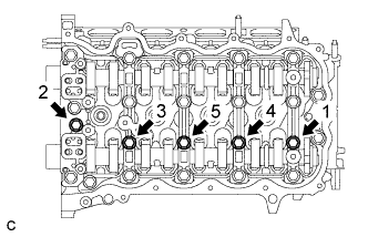
-
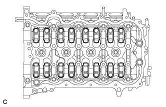
Uniformly loosen and remove the 5 bearing cap bolts in the sequence shown in the illustration.
-
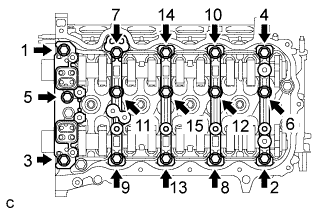
Uniformly loosen and remove the 15 bearing cap bolts in the sequence shown in the illustration.
Note
Uniformly loosen the bolts while keeping the camshaft level.
-
Remove the 5 bearing caps.
Tech Tips
Arrange the removed parts in the correct order.
-
-
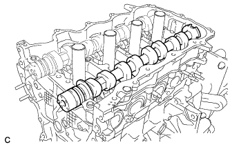
REMOVE NO. 2 CAMSHAFT
-
Remove the No. 2 camshaft.
-
-
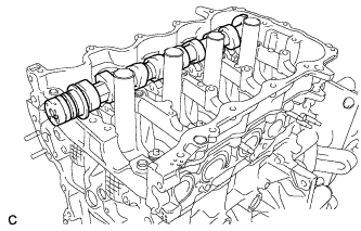
REMOVE CAMSHAFT
-
Remove the camshaft.
-
-
REMOVE NO. 1 VALVE ROCKER ARM SUB-ASSEMBLY
-
Remove the 16 valve rocker arms.
Tech Tips
Arrange the removed parts in the correct order.
-
-
REMOVE VALVE LASH ADJUSTER ASSEMBLY
-
Remove the 16 valve lash adjusters from the cylinder head.
Tech Tips
Arrange the removed parts in the correct order.
-
-
REMOVE CAMSHAFT HOUSING SUB-ASSEMBLY
-
Remove the 3 bolts.
-
Text in Illustration *1 Protective Tape Using a screwdriver with its tip wrapped with protective tape, remove the camshaft housing by prying between the cylinder head and camshaft housing.
Note
Be careful not to damage the contact surfaces of the cylinder head and camshaft housing.
-
-
REMOVE CYLINDER HEAD SUB-ASSEMBLY
-
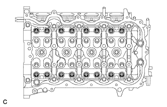
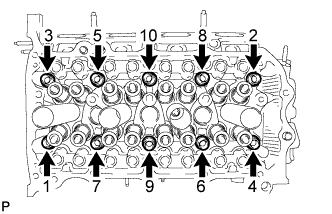
Using several steps, uniformly loosen and remove the 10 cylinder head bolts and 10 plate washers with a 10 mm bi-hexagon wrench in the sequence shown in the illustration.
Note
Head warpage or cracking could result from removing the bolts in the wrong order.
-
Using a screwdriver with its tip wrapped with protective tape, pry between the cylinder head and cylinder block, and remove the cylinder head.
Note
Be careful not to damage the contact surfaces of the cylinder head and cylinder block.
-
-
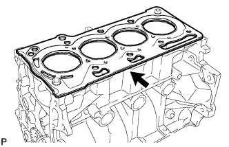
REMOVE CYLINDER HEAD GASKET
-
Remove the cylinder head gasket.
-
-
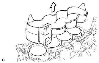
REMOVE CYLINDER BLOCK WATER JACKET SPACER
-
Remove the cylinder block water jacket spacer from the cylinder block.
-
-
REMOVE NO. 2 OIL PAN SUB-ASSEMBLY
-
Remove the oil pan drain plug and gasket from the No. 2 oil pan.
-
Remove the 9 bolts.
-
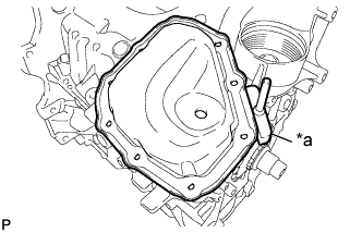
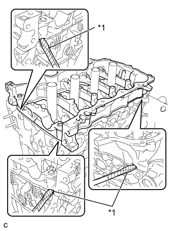
Text in Illustration *1 Oil Pan Seal Cutter Insert the blade of the oil pan seal cutter between the oil pans as shown in the diagram. Cut through the applied sealer and remove the No. 2 oil pan.
Note
Be careful not to damage the contact surfaces of the oil pan.
-
-
REMOVE OIL PAN SUB-ASSEMBLY
-
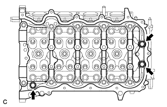
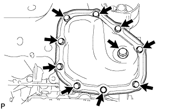
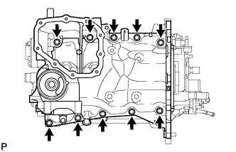
Uniformly loosen and remove the 10 bolts.
-
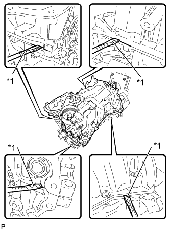
Text in Illustration *1 Protective Tape Using a screwdriver with its tip wrapped with protective tape, remove the oil pan by prying between the oil pan and cylinder block.
Note
Be careful not to damage the contact surfaces of the crankcase and cylinder block.
-
Remove the gasket from the cylinder block.
-
-
REMOVE NO. 1 OIL PAN BAFFLE PLATE
-
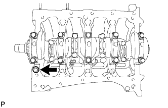
Remove the 6 bolts and the No. 1 oil pan baffle plate from the oil pan.
-
-
REMOVE OIL STRAINER SUB-ASSEMBLY
-
Remove the 2 bolts and the oil strainer from the oil pan.
-