FRONT CRANKSHAFT OIL SEAL INSTALLATION

-
INSTALL TIMING CHAIN COVER OIL SEAL
-
Apply MP grease to the lip of a new timing chain cover oil seal.
Note
Keep the lip free of foreign matter.
-
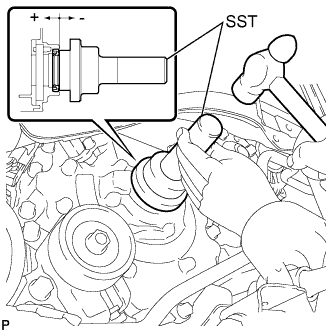
Using SST and a hammer, tap in the timing chain cover oil seal until its surface is flush with the timing chain cover edge.
- SST
- 09223-22010
Oil seal tap in depth -0.5 to 1.0 mm (-0.0197 to 0.0394 in.) Note
-
Do not tap the oil seal at an angle.
-
Wipe off extra grease from the crankshaft.
-
-
INSTALL CRANKSHAFT PULLEY ASSEMBLY
-
Align the pulley set key with the key groove of the crankshaft pulley, and then slide on the crankshaft pulley.
- SST
- 09960-10010 ( 09962-01000, 09963-01000 )
-
Using SST, install the crankshaft pulley bolt.
- Torque:
- 128 N*m { 1305 kgf*cm, 94 ft.*lbf }
-
-
INSTALL FAN AND GENERATOR V-RIBBED BELT
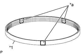
Text in Illustration *1 V-ribbed belt *a Paint Mark
-
Install the V-ribbed belt.
Note
-
There are 2 types of V-ribbed belt. The type to use depends on the type of generator, so be sure to confirm the belt type before installing.
Generator Paint Mark 80 A Blue 100 A Red -
Before installing the V-ribbed belt, check each pulley for any liquid or chips.
-
Check that the ribs of the V-ribbed belt are correctly fitted into the grooves of the pulleys.
-
-
Turn the V-ribbed belt tensioner clockwise and remove the 4 mm bi-hexagon wrench.
-
-
INSTALL NO. 1 V-RIBBED (COOLER COMPRESSOR TO CRANKSHAFT PULLEY) BELT (w/ Air Conditioning System)
-
Temporarily install the No. 1 V-ribbed belt onto each pulley.
Note
-
Before installing the No. 1 V-ribbed belt, check each pulley for any liquid or chips.
-
Check that the ribs of the No. 1 V-ribbed belt are correctly fitted into the grooves of the pulleys.
-
-
-
ADJUST NO. 1 V-RIBBED (COOLER COMPRESSOR TO CRANKSHAFT PULLEY) BELT
-
Turn the adjust bolt B to adjust the tension of No. 1 V-ribbed belt.
Deflection Pressing Force N ( kg, lb) New Belt mm (in.) Used Belt mm (in.) 10
(10, 22)
8.0 to 10.0
(0.315 to 0.394)
10.0 to 12.0
(0.394 to 0.472)
-
Tighten bolt A.
- Torque:
- 44 N*m { 449 kgf*cm, 32 ft.*lbf }
-
-
INSPECT FAN AND GENERATOR V-RIBBED BELT
-
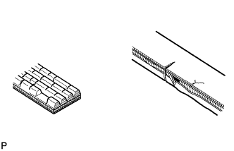
Check the belt for wear, cracks or other signs of damage.
If any of the following defects is found, replace the V-ribbed belt.
Tech Tips
-
The belt is cracked.
-
The belt is worn out to the extent that the cords are exposed.
-
The belt has chunks missing from the ribs.
-
-
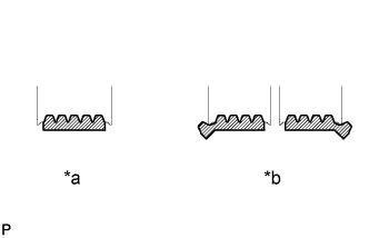
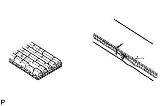
Text in Illustration *a Correct *b Incorrect Check that the belt fits properly in the ribbed grooves.
Tech Tips
Check with your hand to confirm that the belt has not slipped out of the grooves on the bottom of the pulley. If it has slipped out, replace the V-ribbed belt. Install a new V-ribbed belt correctly.
-
-
INSPECT NO. 1 V-RIBBED (COOLER COMPRESSOR TO CRANKSHAFT PULLEY) BELT (w/ Air Conditioning System)
-
Check the belt for wear, cracks or other signs of damage.
If any of the following defects is found, replace the No. 1 V-ribbed belt.
Tech Tips
-
The belt is cracked.
-
The belt is worn out to the extent that the cords are exposed.
-
The belt has chunks missing from the ribs.
-
-
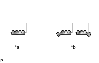
Text in Illustration *a Correct *b Incorrect Check that the belt fits properly in the ribbed grooves.
Tech Tips
Check with your hand to confirm that the belt has not slipped out of the grooves on the bottom to the pulley. If it has slipped out, replace the No. 1 V-ribbed belt. Install a new No. 1 V-ribbed belt correctly.
-
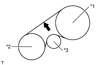
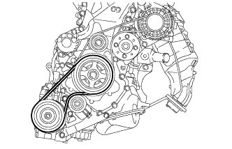
Text in Illustration *1 Crankshaft *2 A/C Compressor *3 Tensioner Inspect the No. 1 V-ribbed belt deflection.
Deflection Pressing Force
N ( kg, lb)
New Belt
mm (in.)
Used Belt
mm (in.)
10
(10, 22)
8.0 to 10.0
(0.315 to 0.394)
10.0 to 12.0
(0.394 to 0.472)
Tech Tips
No. 1 V-ribbed belt tension
New Belt
N (kg, lb)
Used Belt
N (kg, lb)
397 to 593
(40 to 60, 89 to 133)
300 to 398
(31 to 41, 67 to 89)
Note
-
Check the No. 1 V-ribbed belt deflection at the specified point.
-
When installing a new belt, set its deflection value as specified.
-
When checking a belt used for over 5 minutes, confirm that the deflection value is within the specified range for a used belt.
-
When reinstalling a belt used for over 5 minutes, check whether its deflection value is within the specified range for a used belt.
-
-
-
INSPECT FOR ENGINE OIL LEAK
-
INSTALL NO. 1 ENGINE COVER (w/ No. 1 Engine Cover)
-
Temporarily install the No. 1 engine cover with the 2 bolts and nut.
-
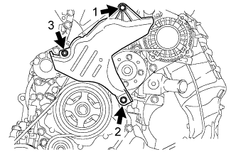
Fully tighten the 2 bolts and nut in the order shown in the illustration.
- Torque:
- 10 N*m { 102 kgf*cm, 7 ft.*lbf }
-
-
INSTALL NO. 1 COOLER COVER (w/ No. 1 Cooler Cover)
-
Temporarily install the No. 1 cooler cover with the 2 nuts.
-
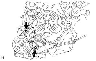
Fully tighten the 2 nuts in the order shown in the illustration.
- Torque:
- 9.8 N*m { 100 kgf*cm, 87 in.*lbf }
-
-
INSTALL NO. 3 ENGINE UNDER COVER
-
Install the No. 3 engine under cover with the 3 clips.
-
-
INSTALL FRONT WHEEL RH
- Torque:
- 103 N*m { 1050 kgf*cm, 76 ft.*lbf }