CAMSHAFT INSTALLATION

-
INSTALL VALVE LASH ADJUSTER ASSEMBLY
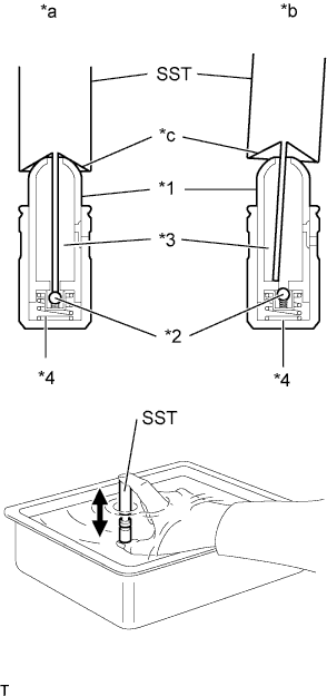
Text in Illustration *1 Plunger *2 Check Ball *3 Low Pressure Chamber *4 High Pressure Chamber *a Correct *b Incorrect *c Taper Part Note
-
Keep the lash adjuster free of dirt and foreign matter.
-
Only use clean engine oil.
-
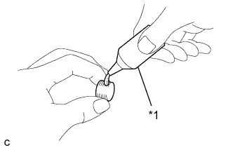
Place the lash adjuster into a container filled with engine oil.
-
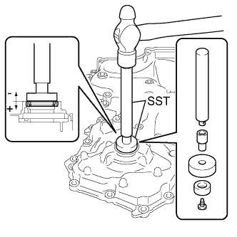
Insert the tip of SST into the lash adjuster plunger and use the tip to press down on the check ball inside the plunger.
- SST
- 09276-75010
-
Squeeze SST and the lash adjuster together to move the plunger up and down 5 to 6 times.
-
Check the movement of the plunger and bleed it.
OK Plunger moves up and down. Note
When bleeding the high-pressure chamber, make sure that the tip of SST is actually pressing the check ball as shown in the illustration. If the check ball is not pressed, the high-pressure chamber will not be bled.
-
After bleeding, remove SST. Then, try to press the plunger quickly and firmly by hand.
OK Plunger is very difficult to move. If the result is not as specified, replace the lash adjuster.
-
Install the lash adjusters.
Note
Install each lash adjuster to the same place it was removed from.
-
-
INSTALL NO. 1 VALVE ROCKER ARM SUB-ASSEMBLY
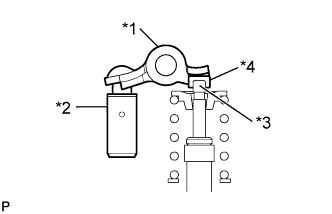
Text in Illustration *1 Valve Rocker Arm *2 Lash Adjuster *3 Valve Stem *4 Valve Stem Cap
-
Apply engine oil to the lash adjuster tip and valve stem cap end.
-
Make sure that the valve rocker arms are installed as shown in the illustration.
-
-
INSTALL CAMSHAFT
-
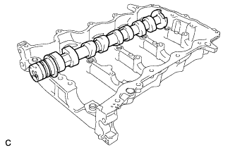
Clean the camshaft journals.
-
Apply a light coat of engine oil to the camshaft journals and camshaft housing.
-
Install the camshaft to the camshaft housing.
-
-
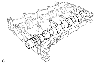
INSTALL NO. 2 CAMSHAFT
-
Clean the camshaft journals.
-
Apply a light coat of engine oil to the camshaft journals and camshaft housing.
-
Install the No. 2 camshaft to the camshaft housing.
-
-
INSTALL CAMSHAFT BEARING CAP
-
Apply engine oil to the bearing caps.
-
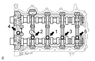
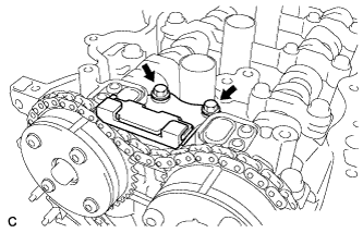
Install the 5 bearing caps to the camshaft housing.
-
Tighten the 5 bolts in the order shown in the illustration.
- Torque:
- 16 N*m { 163 kgf*cm, 12 ft.*lbf }
-
-
INSTALL CAMSHAFT HOUSING SUB-ASSEMBLY
-
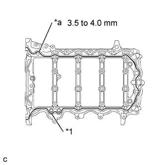
Text in Illustration *1 Seal Packing *a Bead Diameter Apply seal packing in a continuous bead as shown in the illustration.
Seal packing Toyota Genuine Seal Packing Black, Three Bond 1207B or equivalent Bead diameter 3.5 to 4.0 mm (0.138 to 0.158 in.) Note
-
Remove any oil from the contact surfaces.
-
Install the camshaft housing sub-assembly within 3 minutes and tighten the bolts within 15 minutes after applying seal packing.
-
Do not start the engine for at least 2 hours after installing.
-
-
Text in Illustration *1 Timing Mark *a TDC Set the crankshaft in the position (40° BTDC) shown in the illustration.
Note
Turn the crankshaft clockwise when positioning the No. 1 cylinder after the camshaft housing sub-assembly is installed.
Tech Tips
Make sure that the timing mark of the crankshaft is positioned as shown in the illustration.
-
Set the camshaft and No. 2 camshaft as shown in the illustration.
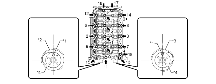
Text in Illustration *1 Knock Pin *2 Camshaft *3 No. 2 Camshaft *4 No. 1 Cylinder Cam Tech Tips
Make sure that the knock pin of the camshaft is positioned as shown in the illustration.
-
Install the camshaft housing and tighten the 18 bolts in the order shown in the illustration.
- Torque:
- 28 N*m { 286 kgf*cm, 21 ft.*lbf }
Note
-
After installing the camshaft housing, make sure that the cam lobes are positioned as shown in the illustration.
-
If any of the bolts are loosened during installation, remove the camshaft housing, clean the installation surfaces, and reapply seal packing.
-
If the camshaft housing is removed because any of the bolts are loosened during installation, make sure that the previously applied seal packing does not enter any oil passages.
-
After installing the camshaft housing, wipe off any seal packing that seeped out from between the housing and the cylinder head.
-
-
INSTALL CAMSHAFT TIMING GEAR ASSEMBLY
-
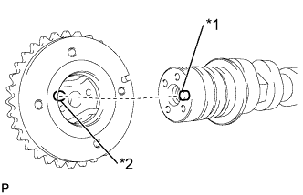
Text in Illustration *1 Straight Pin *2 Key Groove Check that the knock pin is installed on the camshaft.
-
Put the camshaft timing gear and camshaft together by aligning the key groove and straight pin.
Note
-
Do not forcefully push in the camshaft timing gear assembly. This may cause the camshaft knock pin tip to damage the installation surface of the camshaft timing gear assembly.
-
Do not turn the camshaft timing gear in the retard direction (clockwise).
-
-
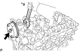
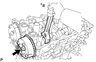
Text in Illustration *a Hold Tighten the flange bolt with the camshaft timing gear secured in place.
- Torque:
- 54 N*m { 551 kgf*cm, 40 ft.*lbf }
-
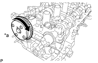
Text in Illustration *a Lock Check that the camshaft timing gear can move in the retard direction (clockwise) and locks in the most retarded position.
-
-
INSTALL CAMSHAFT TIMING EXHAUST GEAR ASSEMBLY
-
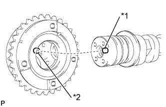
Text in Illustration *1 Straight Pin *2 Key Groove Check that the knock pin is installed on the No. 2 camshaft.
-
Put the camshaft timing exhaust gear and No. 2 camshaft together by aligning the key groove and straight pin.
Note
Do not forcefully push in the camshaft timing gear assembly. This may cause the camshaft knock pin tip to damage the installation surface of the camshaft timing gear assembly.
-
Text in Illustration *a Hold Tighten the flange bolt with the camshaft timing exhaust gear secured in place.
- Torque:
- 54 N*m { 551 kgf*cm, 40 ft.*lbf }
-
Make sure that the camshaft timing exhaust gear is locked.
-
-
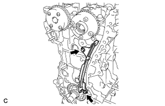
INSTALL TIMING CHAIN GUIDE
-
Install the timing chain guide with the 2 bolts.
- Torque:
- 10 N*m { 102 kgf*cm, 7 ft.*lbf }
-
-
INSTALL CHAIN SUB-ASSEMBLY
-
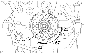
Text in Illustration *1 Timing Mark *a TDC Set the crankshaft in the position (90° ATDC) shown in the illustration.
Tech Tips
Make sure that the timing mark of the crankshaft is positioned as shown in the illustration.
-
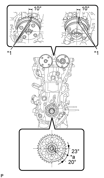
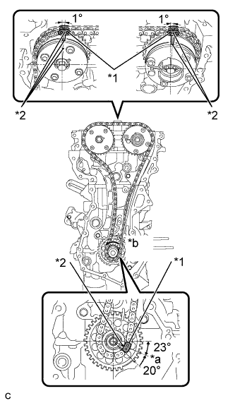
Text in Illustration *1 Timing Mark *a TDC Set the camshaft timing gear and camshaft timing exhaust gear in the positions (20° ATDC) shown in the illustration.
-
Set the crankshaft in the position (20° ATDC) shown in the illustration.
-
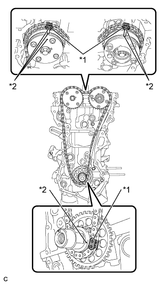
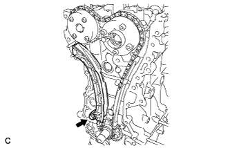
Text in Illustration *1 Mark Plate *2 Timing Mark Align the timing marks of the camshaft with the mark plates of the timing chain and install the timing chain.
-
-
INSTALL TIMING CHAIN TENSION ARM
-
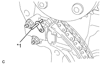
Install the timing chain tension arm with the bolt.
- Torque:
- 21 N*m { 214 kgf*cm, 15 ft.*lbf }
-
-
INSTALL NO. 1 CHAIN TENSIONER ASSEMBLY
-
Install a new gasket to the cylinder head.
-
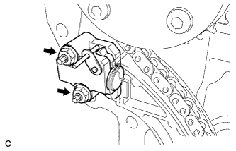
Install the No. 1 chain tensioner with the 2 nuts.
- Torque:
- 10 N*m { 102 kgf*cm, 7 ft.*lbf }
-
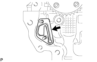
Install the No. 2 chain vibration damper with the 2 bolts.
- Torque:
- 10 N*m { 102 kgf*cm, 7 ft.*lbf }
-
Text in Illustration *1 Bar Remove the bar from the No. 1 chain tensioner.
-
Text in Illustration *1 Mark Plate *2 Timing Mark *a TDC *b Turn Turn the crankshaft approximately 20° counterclockwise to set it to TDC. Make sure that the timing marks and mark plates are correctly positioned and that the chain is securely fit into the tension arm, guide and vibration damper.
-
-
INSTALL TIMING CHAIN COVER OIL SEAL
-
Using SST and a hammer, tap in a new oil seal until its surface is flush with the timing chain cover edge.
- SST
- 09950-60010 ( 09951-00250, 09951-00410, 09952-06010 )
- 09950-70010 ( 09951-07150 )
Oil seal tap in depth -0.5 to 1.0 mm (-0.0197 to 0.0394 in.) Note
Do not tap the oil seal at an angle.
-
Apply a light coat of MP grease to the timing chain cover oil seal lip.
Note
Keep the seal lip free of foreign matter.
-
-
INSTALL TIMING CHAIN COVER SUB-ASSEMBLY
-
Text in Illustration *1 Adhesive Apply adhesive to 2 or 3 threads of the plug.
Adhesive Toyota Genuine Adhesive 1324, Three Bond 1324 or equivalent -
Using an 8 mm socket hexagon wrench, install the plug.
- Torque:
- 15 N*m { 153 kgf*cm, 11 ft.*lbf }
Note
-
Install the plug within 3 minutes after applying adhesive.
-
Do not start the engine within 1 hour after installation.
-
Remove any old packing material remaining on the sealing surfaces before applying seal packing.
-
Clean and degrease the contact surfaces of the timing chain cover, camshaft housing, cylinder head, cylinder block and oil pan and confirm that no oil, moisture, or other foreign matter remains on the surfaces.
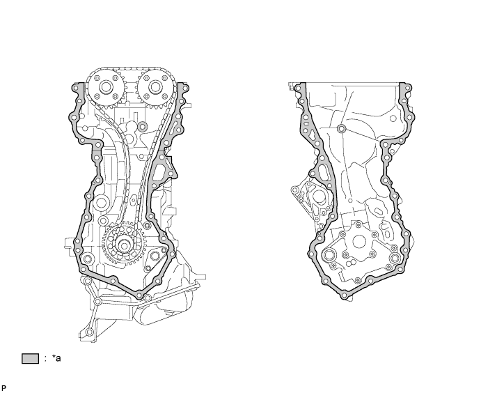
Text in Illustration *a Clean and degrease - - -
Install 2 new O-rings.
-
Apply seal packing to the timing chain cover as shown in the following illustration.
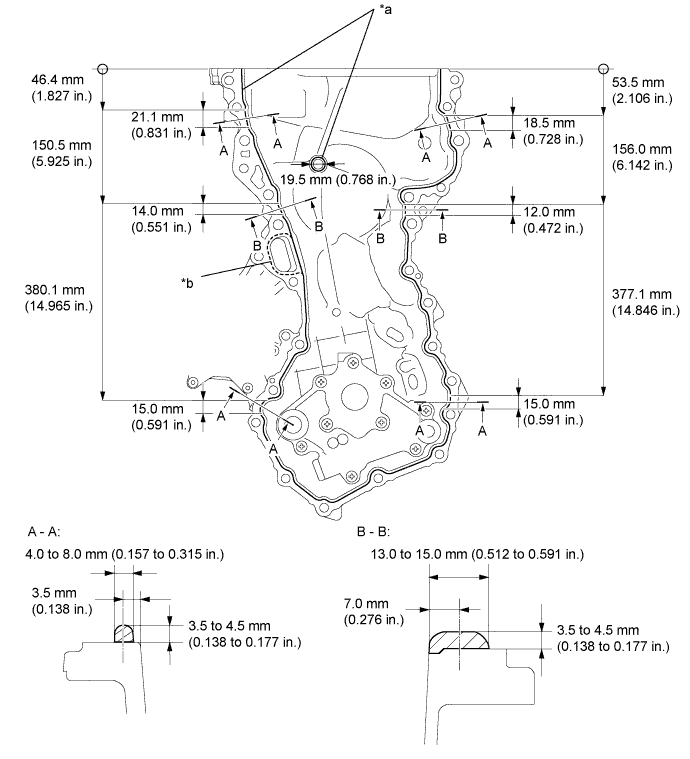
Text in Illustration *a Toyota Genuine Seal Packing Black, Three Bond 1207B or equivalent *b Toyota Genuine Seal Packing Black 1282B, Three Bond 1282B or equivalent Note
-
When there is oil on the contact surfaces, wipe them with oil-free cloth before applying seal packing.
-
Install the chain cover within 3 minutes and tighten the bolts within 10 minutes after applying seal packing.
-
Do not start the engine for at least 2 hours after installing.
Tech Tips
Areas A - A and B - B are the joints between the cylinder block and oil pan, cylinder block and cylinder head, and cylinder head and camshaft housing.
Seal Packing Application Chart Area Seal Packing Diameter Seal Packing Continuous Line Area
Except A - A and B - B
3.5 to 4.5 mm
(0.138 to 0.177 in.)
Toyota Genuine Seal Packing Black,
Three Bond 1207B or equivalent
Dashed Line Area 2.0 to 3.0 mm
(0.0787 to 0.118 in.)
Toyota Genuine Seal Packing Black 1282B,
Three Bond 1282B or equivalent
-
-
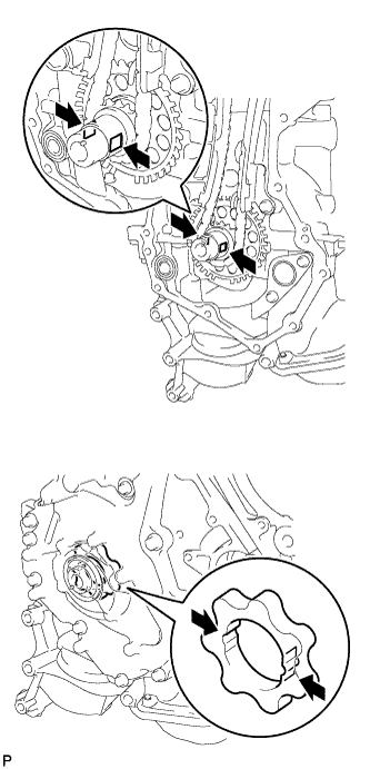
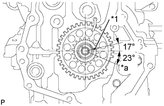
Align the oil pump drive rotor the crankshaft as shown in the illustration.
-
Install the spline and chain cover to the crankshaft.
-
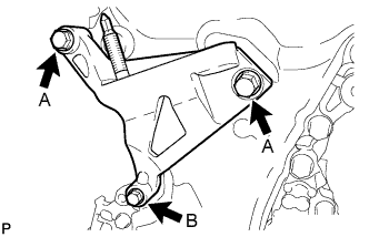
Temporarily install the engine mounting bracket RH with the 3 bolts.
Bolt Length Item Length Bolt A 80 mm (3.150 in.) Bolt B 40 mm (1.575 in.) -
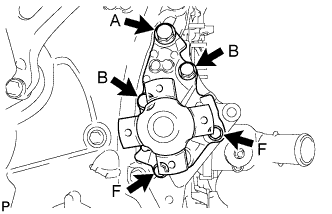
Temporarily install the water pump and a new water pump gasket to the timing chain cover with the 5 bolts.
Bolt Length Item Length Bolt A 40 mm (1.575 in.) Bolt B 40 mm (1.575 in.) Bolt F 18 mm (0.709 in.) -
Fully tighten the 2 F bolts shown in the illustration.
- Torque:
- Bolt F
- 21 N*m { 214 kgf*cm, 15 ft.*lbf }
-
Temporarily tighten the timing chain cover with the 21 bolts and a seal washer.
Text in Illustration *1 Seal Washer - - Tech Tips
-
Apply adhesive to the threads of bolt E.
-
Apply adhesive to bolt E more than 7.0 mm (0.275 in.) from the bolt tip.
Bolt E Toyota Genuine Adhesive 1324, Three Bond 1324 or equivalent Bolt Length Item Length Bolt A 40 mm (1.575 in.) Bolt B 40 mm (1.575 in.) Bolt C 35 mm (1.378 in.) Bolt D, E 25 mm (0.984 in.) -
-
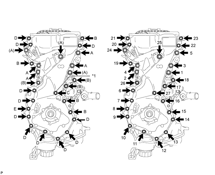
Fully tighten the timing chain cover with the 27 bolts as shown in the illustration.
- Torque:
- Bolt A
- 71 N*m { 724 kgf*cm, 52 ft.*lbf }
- Bolt B, D, E
- 24 N*m { 245 kgf*cm, 18 ft.*lbf }
- Bolt C
- 10 N*m { 102 kgf*cm, 7 ft.*lbf }
-
-
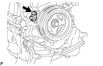
INSTALL CRANKSHAFT PULLEY
-
Align the pulley set key with the key groove of the crankshaft pulley, and then slide on the crankshaft pulley.
-
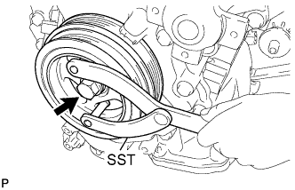
Using SST, install the crankshaft pulley bolt.
- SST
- 09960-10010 ( 09962-01000, 09963-01000 )
- Torque:
- 128 N*m { 1305 kgf*cm, 94 ft.*lbf }
-
-
INSTALL WATER PUMP PULLEY
- SST
- 09960-10010 ( 09962-01000, 09963-00600 )
-
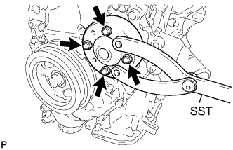
Using SST, install the water pump pulley with the 4 bolts.
- SST
- 09960-10010 ( 09963-00600 )
- Torque:
- 10 N*m { 102 kgf*cm, 7 ft.*lbf }
-
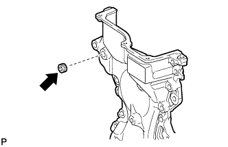
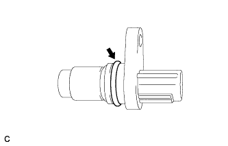
INSTALL CRANKSHAFT POSITION SENSOR
-
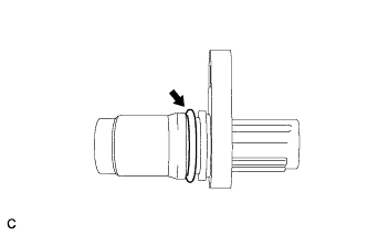
Apply a light coat of engine oil to the O-ring of the sensor.
-
Install the crankshaft position sensor with the bolt.
- Torque:
- 10 N*m { 102 kgf*cm, 7 ft.*lbf }
-
-
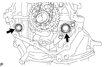
INSTALL CAMSHAFT BEARING CAP OIL HOLE GASKET
-
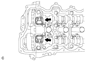
Install the 2 new camshaft bearing cap oil hole gaskets to the No. 1 camshaft bearing cap.
-
-
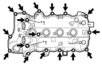
INSTALL CYLINDER HEAD COVER SUB-ASSEMBLY
-
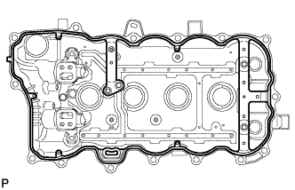
Install a new gasket to the cylinder head cover.
Note
Remove any oil from the contact surfaces.
-
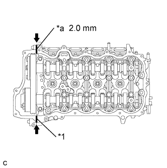
Text in Illustration *1 Seal Packing *a Bead Diameter Apply seal packing as shown the illustration.
Seal packing Toyota Genuine Seal Packing Black, Three Bond 1207B or equivalent Bead diameter 2.0 mm (0.0787 in.) Note
-
Remove any oil from the contact surfaces.
-
Install the cylinder head cover within 3 minutes and tighten the bolts within 15 minutes after applying seal packing.
-
Do not start the engine for at least 2 hours after the installation.
-
-
Text in Illustration *1 Seal Washer Temporarily install the cylinder head cover with 2 new seal washers and the 17 bolts.
-
Apply a light coat of engine oil to the O-rings of the No. 1 crankshaft position sensors.
-
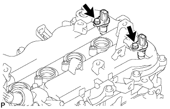
Temporarily install the 2 No. 1 crankshaft position sensors with the 2 bolts.
-
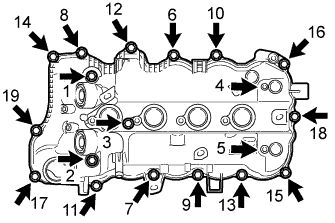
Fully tighten the 20 bolts in the order shown in the illustration.
- Torque:
- 10 N*m { 102 kgf*cm, 7 ft.*lbf }
-
-
INSTALL V-RIBBED BELT TENSIONER ASSEMBLY
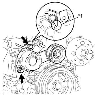
*1 Stopper
-
Install the V-ribbed belt tensioner and engine cover bracket with the 2 bolts.
Note
Attach stopper of the bracket to the auto tensioner.
- Torque:
- 21 N*m { 214 kgf*cm, 15 ft.*lbf }
-
-
INSTALL NO. 2 IDLE PULLEY ASSEMBLY (w/ Air Conditioning System)
-
Temporarily install the No. 2 idle pulley with the 4 bolts.
-
Fully tighten the 4 bolts in the order shown in the illustration.
- Torque:
- 25 N*m { 250 kgf*cm, 18 ft.*lbf }
-
-
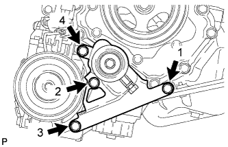
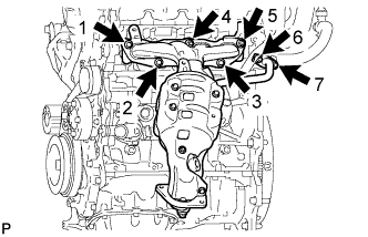
INSTALL NO. 1 WATER BY-PASS PIPE
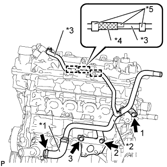
Text in Illustration *1 Water By-Pass Hose *2 No. 1 Water By-pass Pipe *3 No. 2 Water By-Pass Hose *4 Protector *5 Clip
-
Connect the water by-pass hose to the water inlet with the clip.
Note
Install the clip so that its claws face away from the engine.
-
Temporarily install the No. 1 water by-pass pipe with the 3 bolts.
-
Fully tighten the 3 bolts in the order shown in the illustration.
- Torque:
- 22 N*m { 224 kgf*cm, 16 ft.*lbf }
-
Engage the No. 2 water by-pass hose to the 3 clamps as shown in the illustration.
-
-
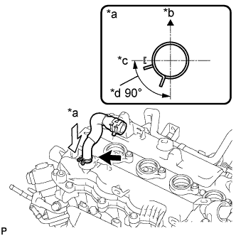
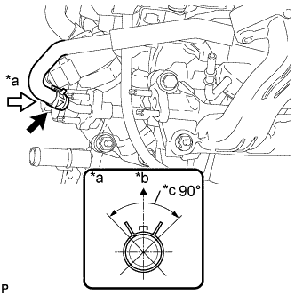
INSTALL NO. 2 VENTILATION HOSE
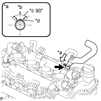
Text in Illustration *a View A *b Upper *c Clip center installation range *d Paint mark of the hose
-
Install the ventilation hose to the cylinder head with the clip.
Note
-
Install the clip so that its claws are within the clip center installation range.
-
The protrusion of the head cover should overlap the paint mark of the hose.
-
-
-
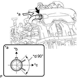
INSTALL VENTILATION HOSE
Text in Illustration *a View A *b Left *c Rear *d Clip center installation range
-
Install the ventilation hose to the cylinder head with the clip.
Note
Install the clip so that its claws are within the clip center installation range.
-
-
INSTALL NO. 1 IGNITION COIL
-
Install the 4 ignition coils with the 4 bolts.
- Torque:
- 10 N*m { 102 kgf*cm, 7 ft.*lbf }
-
-
INSTALL INJECTOR VIBRATION INSULATOR
-
Install 4 new injector vibration insulators onto the cylinder head.
-
-
INSTALL NO. 1 DELIVERY PIPE SPACER
-
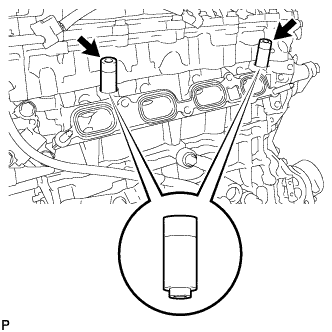
Install the 2 No. 1 delivery pipe spacers onto the cylinder head.
Note
Install the No. 1 delivery pipe spacers in the correct direction.
-
-
INSTALL FUEL INJECTOR ASSEMBLY
-
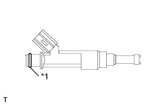
Text in Illustration *1 O-Ring Apply a light coat of gasoline or spindle oil to new O-rings, then install one onto each fuel injector assembly.
-
Apply a light coat of gasoline or spindle oil to the contact surfaces of the fuel delivery pipe and the O-ring of the fuel injector assembly.
-
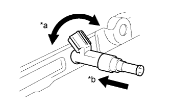
Text in Illustration *a Turn *b Push While turning the fuel injector assembly left and right, install it onto the fuel delivery pipe sub-assembly.
Note
-
Do not twist the O-ring.
-
After installing the fuel injectors, check that they turn smoothly. If not, replace the O-ring with a new one.
-
-
-
INSTALL FUEL DELIVERY PIPE
-
Install the fuel delivery pipe with the 4 fuel injectors, and then temporarily install the 2 bolts.
Note
-
Do not drop the fuel injectors when installing the fuel delivery pipe sub-assembly.
-
Check that the fuel injector assemblies rotate smoothly after installing the fuel delivery pipe sub-assembly.
-
-
Tighten the 2 bolts to the specified torque.
- Torque:
- 28 N*m { 286 kgf*cm, 21 ft.*lbf }
-
-
INSTALL EGR VALVE ASSEMBLY
-
Install a new EGR valve gasket onto the cylinder head.
-
Install the EGR valve with the bolt and 2 new nuts.
- Torque:
- 28 N*m { 286 kgf*cm, 21 ft.*lbf }
-
-
INSTALL ENGINE OIL LEVEL DIPSTICK GUIDE
-
Install a new O-ring to the oil level dipstick guide.
Tech Tips
Apply engine oil to the O-ring and install the oil level dipstick guide into the oil pan.
-
Temporarily install the engine oil level dipstick guide with the 2 bolts.
-
Fully tighten the 2 bolts in the order shown in the illustration.
- Torque:
- 18 N*m { 184 kgf*cm, 13 ft.*lbf }
-
-
INSTALL ENGINE OIL LEVEL DIPSTICK
-
INSTALL NO. 4 ENGINE WIRE
-
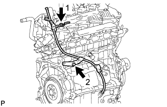
Engage the 7 clamps and install the No. 4 engine wire.
-
Install the ground bolt.
- Torque:
- 8.4 N*m { 86 kgf*cm, 74 in.*lbf }
-
Connect the 4 fuel injector connectors.
-
Connect the 4 ignition coil connectors.
-
Connect the 2 camshaft timing oil control valve connectors.
-
-
INSTALL INTAKE MANIFOLD ASSEMBLY
-
Install a new No. 2 intake manifold to head gasket onto the cylinder head.
-
Install the EGR delivery chamber onto the No. 2 intake manifold to head gasket.
-
Install a new intake manifold to head gasket onto the EGR delivery chamber.
-
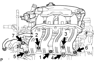
Temporarily install the intake manifold with the 5 bolts and 2 nuts.
-
Fully tighten the 5 bolts and 2 nuts in the order shown in the illustration.
- Torque:
- 28 N*m { 286 kgf*cm, 21 ft.*lbf }
-
-
INSTALL EGR PIPE CONNECTOR
-
Install 2 new EGR pipe gaskets onto the intake manifold and the EGR valve.
-
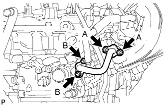
Temporarily install the EGR pipe connector with the 4 nuts.
-
Fully tighten the A nuts first, and then tighten nut B.
- Torque:
- 10 N*m { 102 kgf*cm, 7 ft.*lbf }
-
-
INSTALL INTAKE MANIFOLD STAY
-
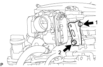
Temporarily install the intake manifold stay with the 2 bolts.
-
Fully tighten the 2 bolts in the order shown in the illustration.
- Torque:
- 28 N*m { 286 kgf*cm, 21 ft.*lbf }
-
-
CONNECT NO. 4 WATER BY-PASS HOSE
Text in Illustration *a View A *b Upper *c Clip center installation range
-
Connect the No. 4 water by-pass hose to the EGR valve with the clip.
Note
Install the clip so that its claws are within the clip center installation range.
-
-
CONNECT NO. 2 WATER BY-PASS HOSE
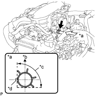
Text in Illustration *a View A *b Upper *c Clip installation range *d Paint mark of the hose
-
Connect the No. 2 water by-pass hose to the throttle body with the clip.
Note
-
Install the clip so that its claws are within the clip installation range.
-
Line up the rib of the throttle with motor body assembly with the center of the paint mark.
-
-
-
CONNECT VENTILATION HOSE
Text in Illustration *a View A *b Upper *c Left *d Clip center installation range
-
Connect the ventilation hose to the intake manifold with the clip.
Note
Install the clip so that its claws are within the clip center installation range.
-
-
INSTALL EXHAUST MANIFOLD CONVERTER SUB-ASSEMBLY
-
Install the new exhaust manifold to head gasket and the new inlet EGR gasket onto the cylinder head.
-
Temporarily install the exhaust manifold converter with the 3 bolts and 4 nuts.
-
Fully tighten the 3 bolts and 4 nuts in the order shown in the illustration.
- Torque:
- 28 N*m { 286 kgf*cm, 21 ft.*lbf }
-
-
INSTALL MANIFOLD STAY
-
Temporarily install the manifold stay with the bolt and nut.
-
Fully tighten the bolt and nut in the order shown in the illustration.
- Torque:
- 28 N*m { 286 kgf*cm, 21 ft.*lbf }
-
-
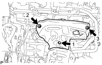
INSTALL NO. 1 EXHAUST MANIFOLD HEAT INSULATOR
-
Temporarily install the exhaust manifold heat insulator with the bolt and 2 nuts.
-
Fully tighten the bolt and 2 nuts in the order shown in the illustration.
- Torque:
- 10 N*m { 102 kgf*cm, 7 ft.*lbf }
-
-
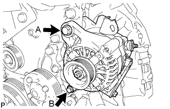
INSTALL GENERATOR ASSEMBLY
-
Install the generator with the 2 bolts.
- Torque:
- Bolt A
- 54 N*m { 551 kgf*cm, 40 ft.*lbf }
- Bolt B
- 21 N*m { 214 kgf*cm, 15 ft.*lbf }
-
-
SUSPEND ENGINE ASSEMBLY
-
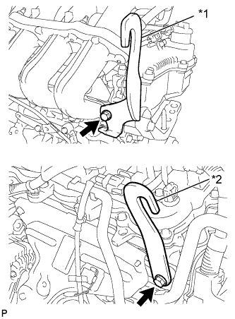
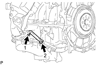
Text in Illustration *1 No. 1 Engine Hanger *2 No. 2 Engine Hanger Install the 2 engine hangers with the 2 bolts.
- Torque:
- 43 N*m { 438 kgf*cm, 32 ft.*lbf }
Tech Tips
Part Name Part No. No. 1 Engine Hanger 12281-47010 No. 2 Engine Hanger 12282-47010 Bolt 91552-81040 -
Attach the engine sling device to the engine hangers.
-
-
REMOVE ENGINE STAND