ENGINE ON-VEHICLE INSPECTION

-
INSPECT ENGINE COOLANT
-
Remove the water filler cap sub-assembly.
CAUTION:
To avoid the danger of being burned, do not remove the water filler cap sub-assembly while the engine and radiator assembly are still hot.
Thermal expansion will cause hot engine coolant and steam to blow out from the radiator assembly.
-
Check for excessive deposits of rust or scale around the water filler cap sub-assembly and radiator filler hole. The engine coolant should be free of oil.
If excessively dirty, replace the engine coolant.
-
Reinstall the water filler cap sub-assembly.
-
-
INSPECT ENGINE OIL
-
Check engine oil level.
-
Warm up the engine, stop the engine and wait 5 minutes. The oil level should be between the dipstick's low level mark and full level mark. If low, check for leakage and add oil up to the full level mark.
Note
Do not fill engine oil above the full level mark.
-
-
Check engine oil quality.
-
Check the oil for deterioration, water contamination, discoloration and thinning. If the quality is visibly poor, replace the oil.
-
-
-
INSPECT BATTERY
-
Check the battery for damage and deformation. If severe damage, deformation or leak is found, replace the battery.
-
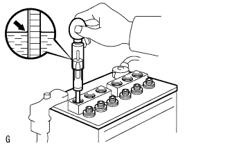
Check the volume of electrolyte quantity in each cell.
-
For batteries that are maintenance-free:
-
If the electrolyte volume is below the lower line, replace the battery.
-
If the electrolyte volume is above the lower line, check the battery voltage when cranking the engine.
-
If the voltage is less than 9.6 V, recharge or replace the battery.
Tech Tips
Before checking the battery voltage, turn off all the electrical systems (headlights, blower motor, rear defogger, etc.).
-
-
For batteries that are not maintenance-free:
-
If the electrolyte volume is below the lower line, add distilled water to each cell. Then, recharge the battery and check the electrolyte specific gravity.
Standard specific gravity 1.25 to 1.29 at 20°C (68°F) If the electrolyte volume is above the lower line, check the battery voltage when cranking the engine. If the battery voltage is less than 9.6 V, recharge or replace the battery.
Tech Tips
Before checking the battery voltage, turn off all the electrical systems (headlights, blower motor, rear defogger, etc.).
-
-
-
-
INSPECT AIR CLEANER FILTER ELEMENT SUB-ASSEMBLY
-
Remove the air cleaner and hose Click here.
-
Remove the air cleaner filter element sub-assembly.
-
Visually check that the air cleaner filter is not excessively damaged or oily. If necessary, replace the air cleaner filter.
Tech Tips
-
If there is any dirt or a blockage in the air cleaner filter element sub-assembly, clean it with compressed air.
-
If any dirt or a blockage remains even after cleaning the air cleaner filter element sub-assembly with compressed air, replace it.
-
-
Install the air cleaner filter element sub-assembly.
-
Install the air cleaner and hose Click here.
-
-
INSPECT V-RIBBED BELT TENSIONER ASSEMBLY
-
Remove the V-ribbed belt Click here.
-
Check that nothing is caught in the tensioner by turning it clockwise and counterclockwise. If a malfunction exists, replace the tensioner.
-
Install the V-ribbed belt Click here.
-
-
INSPECT SPARK PLUG
Note
-
Do not use a wire brush for cleaning.
-
Do not attempt to adjust the electrode gap of a used spark plug.
-
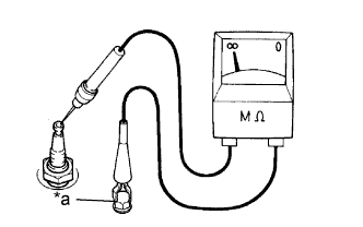
Text in Illustration *a Ground Check the electrode.
-
Measure the insulation resistance.
Standard Resistance 10 MΩ or more Tech Tips
-
If the result is not as specified, clean the spark plug with a spark plug cleaner and measure the resistance again.
-
If a megohmmeter is not available, perform the following simple inspection instead.
-
-
-
Alternative inspection method:
-
Quickly accelerate the engine to 4000 rpm 5 times.
-
Remove the spark plug.
-
Visually check the spark plug.
If the electrode is dry, the spark plug is functioning properly. If the electrode is damp, proceed to the next step.
-
-
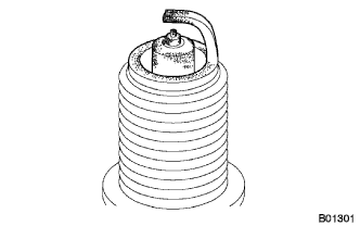
Check the spark plug for any damage to its thread and insulator.
If there is any damage, replace the spark plug.
Recommended Spark Plug Manufacturer Product DENSO SC20HR11 -
Reference:
-
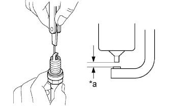
Text in Illustration *a Electrode Gap Check the spark plug electrode gap.
Maximum Electrode Gap for a Used Spark Plug 1.3 mm (0.0512 in.) If the gap is greater than the maximum, replace the spark plug.
Electrode Gap for a New Spark Plug 1.0 to 1.1 mm (0.0394 to 0.0433 in.)
-
-
Clean the spark plug.
If the electrode has traces of wet carbon, clean the electrode with a spark plug cleaner and then dry with compressed air.
Air Pressure 588 kPa (6 kgf/cm2, 85 psi) Duration 20 seconds or less Tech Tips
Only use the spark plug cleaner when the electrode is free of oil. If the electrode has traces of oil, use gasoline to clean off the oil before using the spark plug cleaner.
-
-
INSPECT VALVE LASH ADJUSTER NOISE
-
Rev up the engine several times. Check that the engine does not emit unusual noises. If unusual noises occur, warm up the engine and idle it for over 30 minutes. Then perform the preceding inspection.
Tech Tips
If any defects or problems are found during the preceding inspection, perform lash adjuster inspection Click here.
-
-
INSPECT IGNITION TIMING
Note
-
Check the ignition timing with the cooling fans off.
-
Turn off all electrical systems and the A/C.
-
When checking the ignition timing, the transaxle should be in neutral or park.
-
Warm up and stop the engine.
-
When using the intelligent tester: Check the ignition timing.
-
Connect the intelligent tester to the DLC3.
-
Start the engine and run it at idle.
-
Turn the tester on.
-
Enter the following menus: Powertrain / Engine and ECT / Data List / IGN Advance.
Standard ignition timing Transaxle Ignition Timing Manual Transaxle 0 to 10 degrees BTDC CVT -5 to 5 degrees BTDC Tech Tips
Refer to the intelligent tester operator's manual for further details.
-
Check that the ignition timing advances immediately when the engine speed is increased.
-
Enter the following menus: Powertrain / Engine and ECT / Active Test / Connect the TC and TE1 / ON.
-
Monitor IGN Advance of the Data List.
Standard ignition timing Transaxle Ignition Timing Manual Transaxle 8 to 12 degrees BTDC CVT Note
When checking the ignition timing, the transaxle should be in neutral or park.
Tech Tips
Refer to the intelligent tester operator's manual for further details.
-
Enter the following menus: Connect the TC and TE1 / OFF.
-
Turn the ignition switch off.
-
Disconnect the intelligent tester from the DLC3.
-
-
When not using the intelligent tester:
-
Remove the No. 3 engine under cover (w/ No. 1 Engine Cover).
-
Remove the No. 1 engine cover. (w/ No. 1 Engine Cover)
-
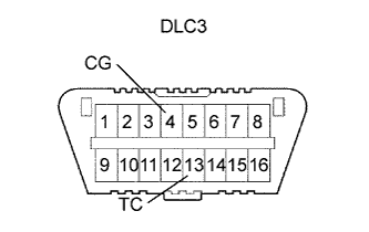
Using SST, connect terminals 13 (TC) and 4 (CG) of the DLC3.
- SST
- 09843-18040
Note
-
Be sure to connect the terminals correctly. Failure to do this can damage the engine.
-
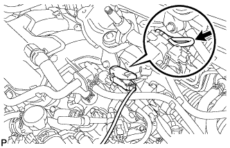
Connect the clip of the timing light to the wire harness.
Note
Use a timing light that detects the primary signal.
-
Inspect the ignition timing at idle.
Standard ignition timing Transaxle Ignition Timing Manual Transaxle 8 to 12 degrees BTDC CVT Note
When checking the ignition timing, the transaxle should be in neutral or park.
Tech Tips
After running the engine at 1000 to 1300 rpm for 5 seconds, check that it returns to idle speed.
-
Disconnect SST from terminals 13 (TC) and 4 (CG) of the DLC3.
-
Inspect the ignition timing at idle.
Standard ignition timing Transaxle Ignition Timing Manual Transaxle 0 to 10 degrees BTDC CVT -5 to 5 degrees BTDC -
Confirm that the ignition timing advances when the engine rpm is increased.
-
Remove the timing light.
-
Install the No. 1 engine cover (w/ No. 1 Engine Cover).
-
Install the No. 3 engine under cover (w/ No. 1 Engine Cover).
-
-
-
INSPECT ENGINE IDLE SPEED
Note
-
Turn all electrical systems and the A/C off.
-
Inspect the idle speed with the cooling fans off.
-
When checking the idle speed, the transaxle should be in neutral or park.
-
Warm up and stop the engine.
-
Connect the intelligent tester to the DLC3.
-
Start the engine and run it at idle.
-
Turn the tester on.
-
Enter the following menus: Powertrain / Engine and ECT / Data List / Engine Speed.
Tech Tips
Refer to the intelligent tester operator's manual for further details.
-
Inspect the engine idle speed.
Standard Idle Speed Transaxle Idling Speed Manual Transaxle 550 to 650 rpm CVT 600 to 700 rpm -
Turn the ignition switch off.
-
Disconnect the intelligent tester from the DLC3.
-
-
INSPECT COMPRESSION
-
Check for DTCs Click here.
Tech Tips
If any DTC is present, perform troubleshooting in accordance with the procedure for that DTC.
-
Warm up and stop the engine.
-
Remove the 4 spark plugs Click here.
Note
Take care to ensure that foreign objects do not enter the intake manifold.
-
Disconnect the 4 fuel injector connectors.
-
Inspect the cylinder compression pressure.
-
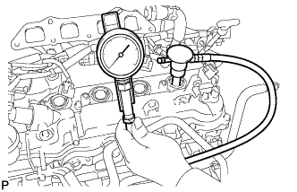
Insert a compression gauge into the spark plug hole.
-
While cranking the engine, measure the compression pressure.
Standard compression pressure 1200 kPa (12.2 kgf/cm2, 174 psi) Minimum pressure 900 kPa (9.1 kgf/cm2, 131 psi) Difference between each cylinder 98 kPa (1.0 kgf/cm2, 14.2 psi) or less Note
-
Use a fully-charged battery so that the engine speed can be increased to 250 rpm or more.
-
Inspect the other cylinders in the same way.
-
Measure the compression in as a short time as possible.
-
-
If the cylinder compression is low, pour a small amount of engine oil into the cylinder through the spark plug hole, and then inspect it again.
Tech Tips
-
If adding oil increases the compression, the piston rings and/or cylinder bore may be worn or damaged.
-
If the pressure stays low, the valve may be stuck or seated improperly, or there may be leakage from the gasket.
-
-
-
Connect the 4 fuel injector connectors.
-
Install the 4 spark plugs Click here.
-
Clear the DTC Click here.
-
Check for DTCs Click here.
Tech Tips
Reinstall the sensors, connectors, etc. and restore the previous vehicle conditions before rechecking for DTCs.
-
-
INSPECT CO/HC
Tech Tips
This check determines whether or not the idle CO/HC complies with local regulations.
-
Start the engine.
-
Run the engine at 2500 rpm for approximately 180 seconds.
-
Insert the CO/HC meter testing probe at least 40 cm (1.3 ft.) into the tailpipe while idling.
-
Check the CO/HC concentration during idle and when the engine is running at 2500 rpm.
Tech Tips
When doing the 2 mode (with the engine idling/ running at 2500 rpm) test, the measurement procedures are determined by applicable local regulations.
If the CO/HC concentration does not comply with local regulations, troubleshoot in the order given below.
-
Check the A/F sensor and heated oxygen sensor operation.
-
See the table below for possible causes, and then inspect the applicable parts and repair them if necessary.
CO HC Problem Possible Cause Normal High Rough idle
-
Faulty ignition:
-
Incorrect timing
-
Fouled, shorted or improperly gapped plugs
-
Incorrect valve clearance
-
Leakage from intake and exhaust valves
-
Leakage from cylinders
Low High Rough idle (Fluctuating HC reading)
-
Vacuum leaks:
-
PCV hoses
-
Intake manifold
-
Throttle body
-
Brake booster line
-
Lean mixture causing misfire
High High Rough idle (Black smoke from exhaust)
-
Restricted air cleaner filter element
-
Plugged PCV valve
-
Faulty EFI system:
-
Faulty pressure regulator
-
Faulty engine coolant temperature sensor
-
Faulty mass air flow meter
-
Faulty ECM
-
Faulty injectors
-
Throttle body
-
-
-