ENGINE ASSEMBLY REMOVAL

Note
-
When the transaxle is removed, be sure to use a new clutch release with bearing cylinder and new installation bolts. Removal of the transaxle allows the compressed clutch release with bearing cylinder to return to its original position, and dust from the moving section could damage the seal of the clutch release with bearing cylinder, possibly causing clutch fluid leaks.
-
After replacing the engine assembly, perform both "Injector Compensation" and "Pilot Quantity Learning Values Reset" functions using the intelligent tester Click here.
-
REFRIGERANT FROM REFRIGERATION SYSTEM (w/ Air Conditioning System)
-
Start up the engine.
-
Switch the A/C on.
-
Turn the blower switch to on.
-
Operate the cooler compressor with an engine speed of approximately 1000 rpm for 5 to 6 minutes to circulate the refrigerant and collect the remaining compressor oil from each component, in the cooler compressor.
-
Stop the engine.
-
Remove the caps from the service valves on the refrigerant line.
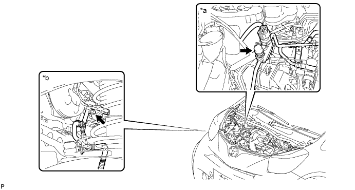
Text in illustration *a Engine room side *b Wheel house side Access to Hi Pressure Side Engine Type RHD LHD 1KR-FE Engine room Engine room 1NR-FE Engine room Engine room 1ND-TV Engine room Engine room Access to Low Pressure Side Engine Type RHD LHD 1KR-FE Wheel house Wheel house 1NR-FE Wheel house Wheel house 1ND-TV Wheel house Wheel house -
Connect the refrigerant recovery unit.
-
Recover the refrigerant from the air conditioning system using a refrigerant recovery unit.
Tech Tips
Use the refrigerant recovery unit in accordance with the manufacturer's instruction manual.
-
-
REMOVE FRONT WHEELS
-
DRAIN ENGINE OIL
-
DRAIN MANUAL TRANSAXLE OIL
-
Drain manual transaxle oil Click here.
-
-
REMOVE ENGINE UNDER COVER
-
Remove the 4 bolts, 4 clips and the engine under cover.
-
-
REMOVE NO. 3 ENGINE UNDER COVER
-
Remove the 3 clips and the No. 3 engine under cover.
-
-
REMOVE FRONT FLOOR COVER LH
-
REMOVE FRONT FLOOR COVER RH
-
REMOVE RADIATOR ASSEMBLY
-
Remove the radiator assembly Click here.
-
-
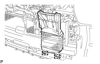
REMOVE RADIATOR RESERVE TANK ASSEMBLY
-
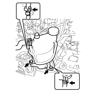
Remove the 2 bolts.
-
Disconnect the air bleed valve.
-
Disconnect the No. 5 water by-pass hose and remove the radiator reserve tank.
-
-
DISCONNECT NO. 2 AIR HOSE
-
Loosen the hose clamp and disconnect the No. 2 air hose.
-
-
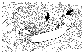
DISCONNECT NO. 3 AIR HOSE
-
Loosen the hose clamp and disconnect the No. 3 air hose.
-
-
REMOVE INTERCOOLER ASSEMBLY
-
Disengage the 2 wire harness clamps and separate the wire harness.
-

Disconnect the vacuum transmitting hose.
-
Disconnect the intake air temperature sensor connector.
-
Disengage the 2 wire harness clamps.
-
Remove the intercooler with the intercooler air duct.
-
-
REMOVE COWL PANEL SUB-ASSEMBLY
-
Remove the cowl panel sub-assembly Click here.
-
-
REMOVE ENGINE COVER ASSEMBLY
-
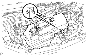
Disengage the 3 claws and remove the engine cover.
-
-
REMOVE AIR CLEANER HOSE ASSEMBLY
-
Remove the air cleaner hose.
-
-
REMOVE BATTERY CLAMP SUB-ASSEMBLY
-
Remove the 2 nuts and the battery clamp.
-
-
REMOVE BATTERY
-
REMOVE BATTERY TRAY
-
REMOVE NO. 2 BATTERY CARRIER
-
Disconnect the 2 wire harness clamps.
-
Remove the 3 bolts and the No. 2 battery carrier.
-
-
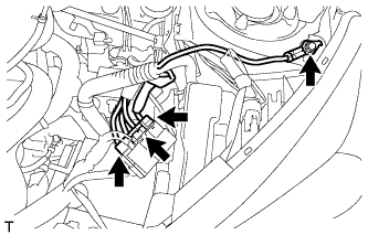
REMOVE FUEL FILTER ASSEMBLY
-
Disconnect the 2 wire harness clamps.
-
Disconnect the connector.
-
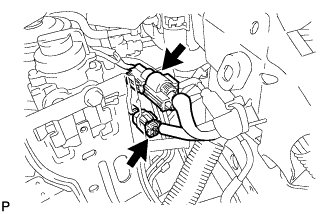
Disconnect the 2 connectors.
-
Disconnect the 2 fuel hose clamps from the fuel filter.
-
Disconnect the 2 fuel hoses.
-
Loosen the fuel filter drain plug to drain fuel.
-
Tighten the fuel filter drain plug.
-
Remove the 2 nuts and fuel filter.
-
-
REMOVE INJECTION PUMP TO FUEL FILTER FUEL HOSE
-
Disengage the hose clamp and remove the injection pump to fuel filter fuel hose.
-
-
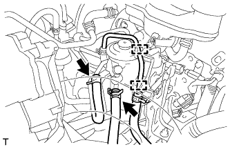
DISCONNECT NO. 2 FUEL HOSE
-
Disconnect the No. 2 fuel hose.
-
-
DISCONNECT ENGINE WIRE
-
Disconnect the 3 connectors from the battery terminal.
-
Remove the engine ground bolt.
-
Disconnect the engine wire from the engine room junction block.
-
Remove the junction block cover.
-
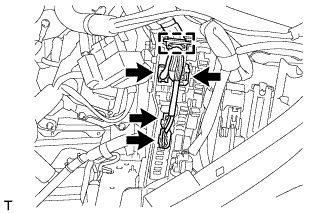
Disconnect the 4 engine wire connectors and clamp.
-
-
-
REMOVE NO. 1 COOLER COVER (w/ No. 1 Cooler Cover)
-
Remove the 2 nuts and the No. 1 cooler cover.
-
-
REMOVE NO. 4 ENGINE COVER (w/ No. 4 Engine Cover)
-
Remove the 2 bolts, nut and the No. 4 engine cover.
-
-
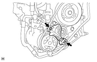
REMOVE NO. 1 V (COOLER COMPRESSOR TO CRANKSHAFT PULLEY) BELT (w/ Air Conditioning System)
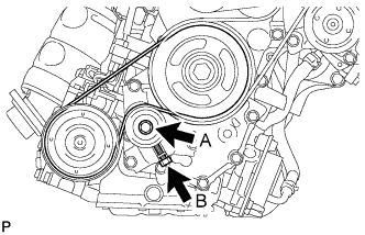
-
Loosen bolts A and B.
-
Remove the No. 1 V belt.
-
-
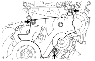
REMOVE NO. 2 IDLE PULLEY ASSEMBLY (w/ Air Conditioning System)
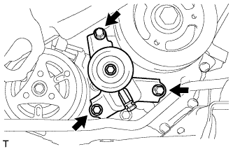
-
Remove the 3 bolts and the No. 2 idle pulley.
-
-
REMOVE FAN AND GENERATOR V BELT
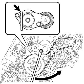
-
Release the V belt tension by turning the V-ribbed belt tensioner counterclockwise, and remove the V belt from the V-ribbed belt tensioner.
-
While turning the V-ribbed belt tensioner counterclockwise, align the holes, and then insert a 5 mm bi-hexagon wrench into the holes to fix the V-ribbed belt tensioner.
-
-
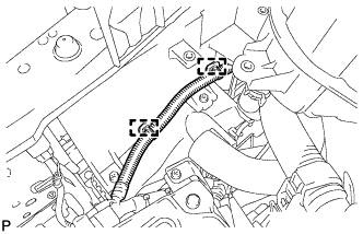
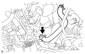
DISCONNECT UNION TO CONNECTOR TUBE HOSE
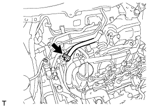
-
Disconnect the union to connector tube hose.
-
-
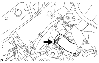
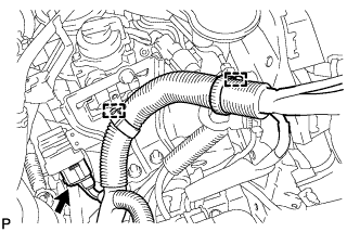
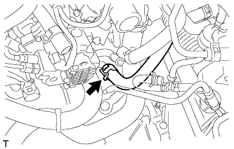
DISCONNECT INLET HEATER WATER HOSE
-
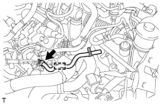
Disconnect the inlet heater water hose.
-
-
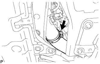
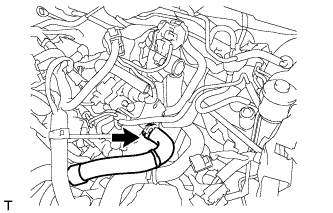
DISCONNECT OUTLET HEATER WATER HOSE
-
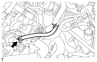
Disconnect the outlet heater water hose.
-
-
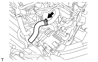
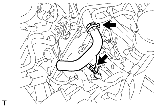
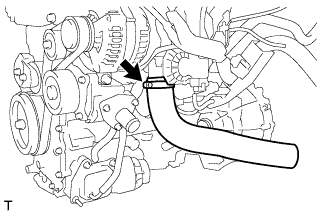
REMOVE NO. 1 RADIATOR HOSE
-
Remove the No. 1 radiator hose.
-
-
REMOVE NO. 2 AIR HOSE
-
Remove the No. 2 air hose.
-
-
REMOVE NO. 1 AIR TUBE
-
Remove the nut and the No. 1 air tube.
-
-
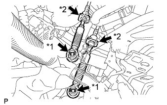
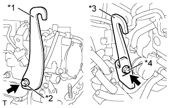
SEPARATE TRANSMISSION CONTROL CABLE ASSEMBLY
-
Remove the 2 clips*1 and disconnect the 2 cables from the transaxle.
-
Remove the 2 clips*2 and disconnect the 2 cables from the control cable bracket.
-
-
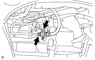
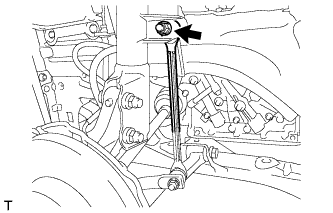
DISCONNECT CLUTCH HOSE
-
Using a union nut wrench 10 mm, disconnect the clutch hose from the clutch release cylinder to flexible hose tube.
-
Remove the clip.
-
-
REMOVE TAIL EXHAUST PIPE ASSEMBLY
-
Remove the tail exhaust pipe assembly Click here.
-
-
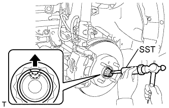
REMOVE FRONT AXLE HUB NUT LH
-
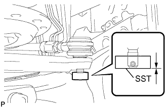
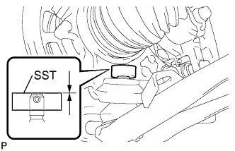
Using SST and a hammer, release the staked part of the axle hub nut.
- SST
- 09930-00010
Note
-
Insert SST into the groove with the flat surface facing up.
-
Do not damage the tip of SST using a grinder.
-
Completely unstake the staked part before removing the axle hub nut.
-
Do not damage the threads of the drive shaft.
-
Using a 30 mm socket wrench, remove the axle hub nut.
-
-
REMOVE FRONT AXLE HUB NUT RH
Tech Tips
Perform the same procedure as above on the opposite side.
-
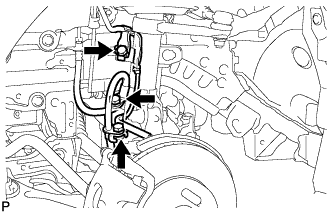
SEPARATE FRONT SPEED SENSOR
-
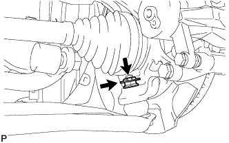
Remove the 3 bolts and separate the speed sensor and flexible hose.
-
Remove the bolt and separate the speed sensor from the steering knuckle.
Note
-
Keep the speed sensor tip and installation area free of foreign matter.
-
Remove the speed sensor without turning it from its original installation angle.
-
-
-
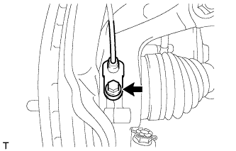
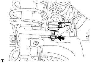
SEPARATE FRONT STABILIZER LINK ASSEMBLY LH
-
Remove the nut and separate the stabilizer link from the shock absorber.
-
-
SEPARATE FRONT STABILIZER LINK ASSEMBLY RH
Tech Tips
Perform the same procedure as above on the opposite side.
-
SEPARATE TIE ROD END SUB-ASSEMBLY LH
-
Remove the cotter pin and castle nut.
-
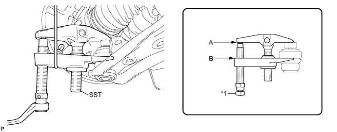
Install SST (spacer B) to the threaded section of the tie rod end.
- SST
- 09960-20010 ( 09961-02060 )
Note
Make sure the upper ends of the threaded section of the tie rod end and SST (spacer B) are aligned.
-
Using SST, separate the tie rod end from the front axle assembly.
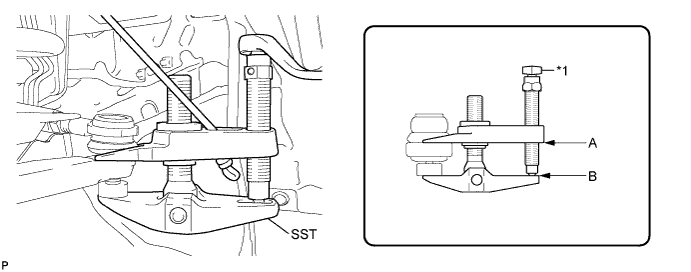
Text in Illustration *1 Place the wrench here - SST
- 09960-20010 ( 09961-02010 )
Note
-
Make sure to tie the string of SST to the vehicle to prevent SST from dropping.
-
Install SST so that A and B are parallel.
-
Be sure to place the wrench on the part indicated in the illustration.
-
Do not damage the ball joint dust cover.
-
Do not damage the front disc brake dust cover.
-
-
SEPARATE TIE ROD END SUB-ASSEMBLY RH
Tech Tips
Perform the same procedure as above on the opposite side.
-
SEPARATE FRONT LOWER SUSPENSION ARM SUB-ASSEMBLY LH
-
Remove the clip and castle nut.
-
Install SST (spacer B) to the threaded section of the lower ball joint.
- SST
- 09960-20010 ( 09961-02060 )
Note
Make sure the upper ends of the threaded section of the lower ball joint and SST (spacer B) are aligned.
-
Using SST, separate the front lower suspension arm from the front axle assembly.
Text in Illustration *1 Place the wrench here - SST
- 09960-20010 ( 09961-02010 )
Note
-
Make sure to tie the string of SST to the vehicle to prevent SST from dropping.
-
Install SST so that A and B are parallel.
-
Be sure to place the wrench on the part indicated in the illustration.
-
Do not damage the lower ball joint dust cover.
-
Do not damage the drive shaft outboard joint boots.
-
Do not damage the front disc brake dust cover.
-
-
SEPARATE FRONT LOWER SUSPENSION ARM SUB-ASSEMBLY RH
Tech Tips
Perform the same procedure as above on the opposite side.
-
SEPARATE FRONT AXLE ASSEMBLY LH
-
Using a plastic hammer, tap the end of the drive shaft and disengage the fitting between the drive shaft and front axle.
Tech Tips
If it is difficult to disengage the fitting, tap the end of the drive shaft with a brass bar and hammer.
-
Push the front axle out of the vehicle to remove the drive shaft from the front axle.
Note
-
Do not push the front axle further out of the vehicle than is necessary.
-
Do not damage the outboard joint boot.
-
Do not damage the speed sensor rotor.
-
Suspend the drive shaft with a piece of string or the equivalent.
-
-
-
SEPARATE FRONT AXLE ASSEMBLY RH
Tech Tips
Perform the same procedure as above on the opposite side.
-
REMOVE FRONT DRIVE SHAFT ASSEMBLY LH
-
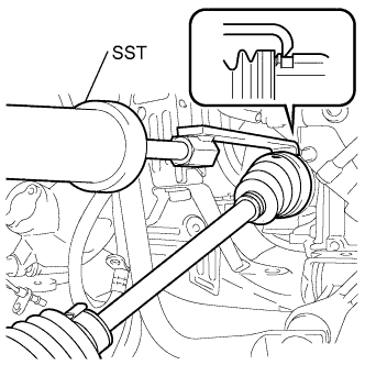
Using SST, remove the drive shaft.
- SST
- 09520-01010
- 09520-24010 ( 09520-32040 )
Note
-
Do not damage the oil seal.
-
Do not damage the inboard joint boot.
-
Do not drop the drive shaft.
-
-
REMOVE FRONT DRIVE SHAFT ASSEMBLY RH
Tech Tips
Use the same procedure for the RH side as for the LH side.
-
REMOVE FRONT FRAME ASSEMBLY
-
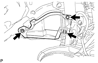
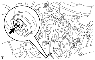
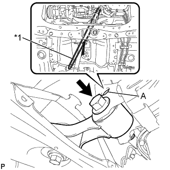
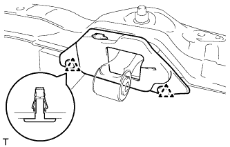
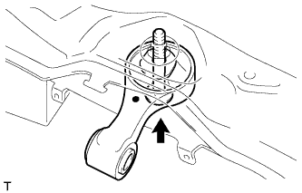
Pass a strong rope through hole (A) in the engine mounting control bracket and tie it securely to the body.
Text in illustration *1 Strong Rope CAUTION:
When the engine moving control rod is separated, the engine assembly moves towards the front of the vehicle and will contact components near the engine if not fastened tightly.
-
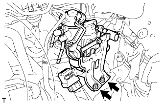
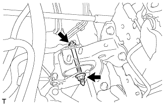
Remove the bolt and separate the engine moving control rod from engine mounting control bracket.
-
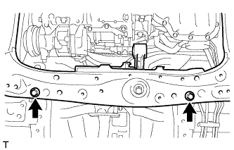
Remove the 2 bolts.
-
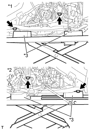
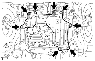
Text in illustration *1 RH Side *2 LH Side *3 Wooden Block Support the front frame assembly with 4 wooden blocks and the jack.
-
Remove the 4 bolts and remove the front frame assembly.
-
-
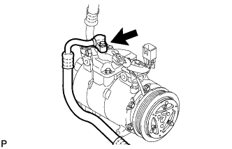
DISCONNECT DISCHARGE HOSE SUB-ASSEMBLY (w/ Air Conditioning System)
-
Remove the bolt and disconnect the discharge hose from the compressor.
-
Remove the O-ring from the discharge hose.
Note
Seal the openings of the disconnected parts using vinyl tape to prevent the entry of moisture and foreign matter.
-
-
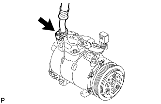
DISCONNECT SUCTION HOSE SUB-ASSEMBLY (w/ Air Conditioning System)
-
Remove the bolt and disconnect the suction hose from the compressor.
-
Remove the O-ring from the suction hose.
Note
Seal the openings of the disconnected parts using vinyl tape to prevent the entry of moisture and foreign matter.
-
-
REMOVE ENGINE MOVING CONTROL ROD COVER (for Cold Area)
Tech Tips
Only perform this procedure when replacement of the engine moving control rod is necessary.
-
Disengage the 2 clips and remove the engine moving control rod cover.
-
-
REMOVE ENGINE MOVING CONTROL ROD
Tech Tips
Only perform this procedure when replacement of the engine moving control rod is necessary.
-
Remove the bolt and engine moving control rod.
-
-
REMOVE ENGINE ASSEMBLY WITH TRANSAXLE
-
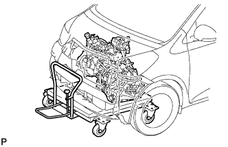
Set the engine lifter.
-
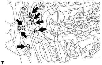
Remove the 5 bolts, 2 nuts and disconnect the engine mounting insulator RH.
-
Remove the through bolt and nut and disconnect the engine mounting insulator LH.
-
Remove the engine assembly with transaxle.
-
Text in Illustration *1 No. 1 Engine Hanger
(Part No. 12281-33050)
*2 Bolt
(Part No. 91552-81050)
*3 No. 2 Engine Hanger
(Part No. 12282-33020)
*4 Bolt
(Part No. 91552-81025)
Install the 2 engine hangers with 2 new bolts as shown in the illustration.
- Torque:
- 40 N*m { 408 kgf*cm, 30 ft.*lbf }
Note
Be sure to use new bolts to install the engine hanger.
-
Using a chain block and engine sling device, hold engine with transaxle.
-
-
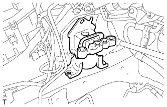
REMOVE ENGINE MOUNTING INSULATOR RH
-
Remove the engine mounting insulator RH.
-
-
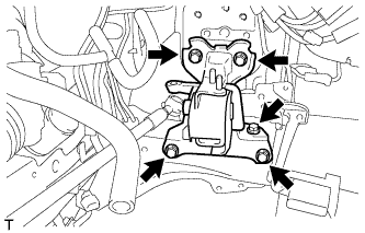
REMOVE ENGINE MOUNTING INSULATOR LH
Tech Tips
Only perform this procedure when replacement of the engine moving mounting insulator LH is necessary.
-
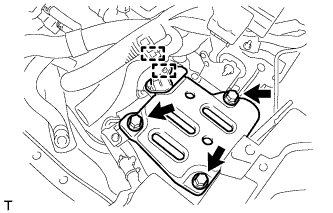
Remove the 5 bolts and engine mounting insulator LH.
-
-
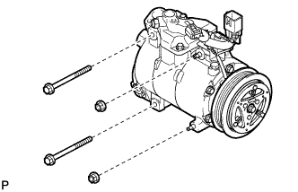
REMOVE COOLER COMPRESSOR ASSEMBLY (w/ Air Conditioning System)
-
Remove the 2 bolts and the 2 nuts.
-
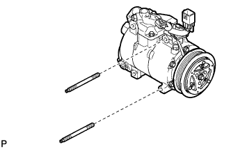
Using a "TORX" socket wrench (E8), remove the 2 stud bolts and the compressor.
-
-
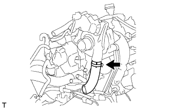
REMOVE NO. 1 AIR HOSE
-
Remove the No. 1 air hose.
-
-
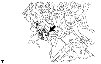
REMOVE NO. 5 WATER BY-PASS HOSE
-
Remove the No. 5 water by-pass hose.
-
-
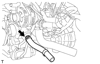
REMOVE NO. 2 RADIATOR HOSE
-
Remove the No. 2 radiator hose.
-
-
REMOVE NO. 3 AIR HOSE
-
Remove the No. 3 air hose.
-
-
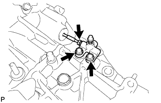
REMOVE STARTER ASSEMBLY
-
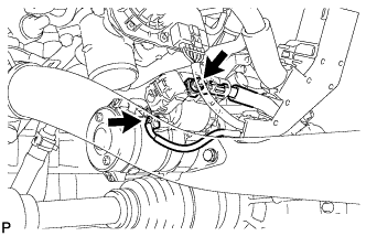
Open the terminal cap.
-
Remove the nut and disconnect the terminal 30.
-
Disconnect the connector.
-
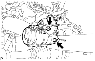
Remove the 2 bolts and the starter assembly.
-
-
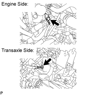
REMOVE ENGINE WIRE
-
Disconnect the 2 ground bolts.
-
Disconnect all the wire harnesses and connectors. Make sure that no wire harnesses are connected to the engine.
-
-
REMOVE NO. 2 TURBO INSULATOR
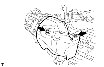
-
Remove the bolt, nut and the No. 2 turbo insulator.
-
-
REMOVE NO. 2 MANIFOLD SUPPORT BRACKET
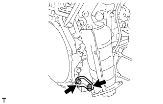
-
Remove the bolt, nut and the No. 2 manifold support bracket.
-
-
REMOVE MANIFOLD SUPPORT BRACKET
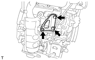
-
Remove the 2 bolts, nut and the manifold support bracket.
-
-
REMOVE EXHAUST MANIFOLD CONVERTER SUB-ASSEMBLY
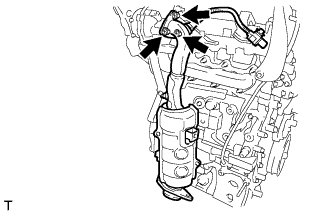
-
Remove the 3 nuts and the exhaust manifold converter.
-
Remove the gasket from the turbocharger.
-
-
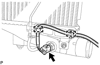
REMOVE CRANKSHAFT POSITION SENSOR
-
Remove the bolt, nut and the No. 1 cylinder block insulator.
-
Remove the crankshaft position sensor.
-
-
REMOVE MANUAL TRANSAXLE ASSEMBLY
-
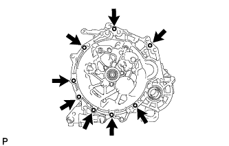
Remove the 8 bolts and the manual transaxle.
-
-
REMOVE BLEEDER TO ACCUMULATOR TUBE
-
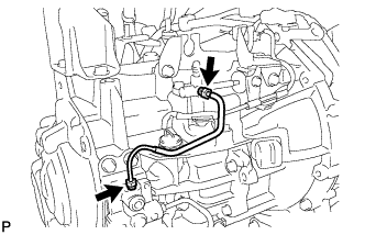
Using a union nut wrench 10 mm, remove the bleeder to accumulator tube.
-
-
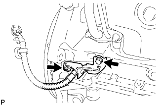
REMOVE CLUTCH RELEASE BLEEDER SUB-ASSEMBLY
-
Using a union nut wrench 10 mm, separate the clutch release bleeder from the bleeder clutch release tube.
-
Remove the 2 bolts and clutch release bleeder.
-
-
REMOVE CLUTCH TUBE BOOT
-
Remove the clutch tube boot from the transaxle.
-
-
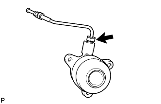
REMOVE BLEEDER CLUTCH RELEASE TUBE
-
Using a union nut wrench 10 mm, remove the clutch release tube from the clutch release with bearing cylinder assembly.
-
-
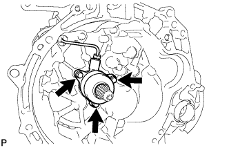
REMOVE CLUTCH RELEASE WITH BEARING CYLINDER ASSEMBLY
-
Remove the 3 bolts and the clutch release with bearing cylinder assembly together with the bleeder clutch release tube.
-
-
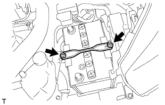
REMOVE CLUTCH COVER ASSEMBLY
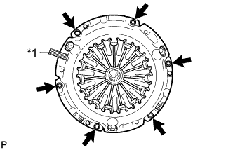
Text in Illustration *1 Matchmark
-
Put the matchmarks on the clutch cover and the flywheel.
-
Loosen each set bolt one turn at a time until the spring tension is released.
-
Remove the set bolts and pull off the clutch cover.
Note
Do not drop the clutch disc.
-
-
REMOVE CLUTCH DISC ASSEMBLY
-
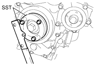
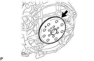
REMOVE FLYWHEEL SUB-ASSEMBLY
-
Hold the crankshaft with SST.
- SST
- 09213-58014
- 09330-00021
-
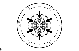
Remove the 6 bolts and flywheel sub-assembly.
-
-
REMOVE NO. 1 CRANKSHAFT POSITION SENSOR PLATE
-
Remove the No. 1 crankshaft position sensor plate.
-