ENGINE ASSEMBLY INSTALLATION

Note
-
When the transaxle is removed, be sure to use a new clutch release with bearing cylinder and new installation bolts. Removal of the transaxle allows the compressed clutch release with bearing cylinder to return to its original position, and dust from the moving section could damage the seal of the clutch release with bearing cylinder, possibly causing clutch fluid leaks.
-
After replacing the engine assembly, perform both "Injector Compensation" and "Pilot Quantity Learning Values Reset" functions using the intelligent tester Click here.
-
INSTALL NO. 1 CRANKSHAFT POSITION SENSOR PLATE
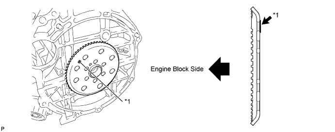
Text in Illustration *1 Mark "RR" - -
-
Install the No. 1 crankshaft position sensor plate.
Note
Install the plate with the concave surface facing the cylinder block, as shown in the illustration.
-
-
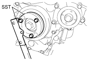
INSTALL FLYWHEEL SUB-ASSEMBLY
-
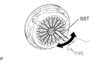
Hold the crankshaft with SST.
- SST
- 09213-58014
- 09330-00021
-
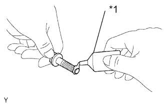
Text in Illustration *1 Adhesive Apply adhesive to the 2 or 3 end threads of the bolts.
Adhesive Toyota Genuine Adhesive 1324, Three Bond 1324 or equivalent. -
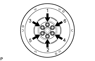
Using several steps, uniformly install and tighten the 6 bolts in the sequence shown in the illustration (Procedure "A").
- Torque:
- 49 N*m { 500 kgf*cm, 36 ft.*lbf }
-
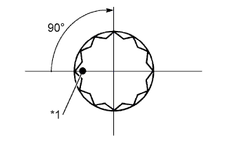
Text in Illustration *1 Paint Mark Mark the bolts with paint as shown in the illustration.
-
Retighten the bolts 90° in the same sequence as procedure "A".
-
Check that the paint marks of each bolt are at a 90° angle from the original position.
-
-
INSTALL CLUTCH DISC ASSEMBLY
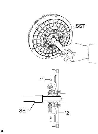
Text in Illustration *1 Clutch disc *2 Flywheel
-
Insert SST into the clutch disc assembly, and then insert them both into the flywheel sub-assembly.
- SST
- 09301-00210
Note
Insert the clutch disc assembly in the correct direction.
-
-
INSTALL CLUTCH COVER ASSEMBLY
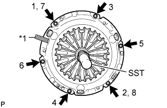
Text in Illustration *1 Matchmark
-
Align the matchmark on the clutch cover assembly with that on the flywheel sub-assembly.
-
Following the procedures shown in the illustration, tighten the 6 bolts in order, starting with the bolt located near the knock pin at the top.
- SST
- 09301-00210
- Torque:
- 19 N*m { 195 kgf*cm, 14 ft.*lbf }
Tech Tips
-
Following the order in the illustration, tighten the bolts evenly one at a time.
-
Move SST up and down, right and left lightly after checking that the disc is in the center, and tighten the bolts.
-
-
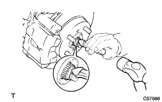
INSPECT AND ADJUST CLUTCH COVER ASSEMBLY
-
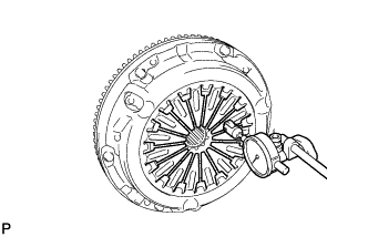
Using a dial indicator with a roller instrument, check the diaphragm spring tip alignment.
Maximum non-alignment 0.5 mm (0.020 in.) -
If the alignment is not as specified, using SST, adjust the diaphragm spring tip alignment.
- SST
- 09333-00013
-
-
INSTALL CLUTCH RELEASE WITH BEARING CYLINDER ASSEMBLY
-
Clean and degrease all installation surfaces for the clutch release with bearing cylinder assembly.
-
Temporarily tighten the bleeder clutch release tube onto the clutch release with bearing cylinder assembly.
-
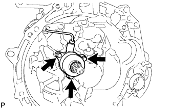
Install the new clutch release with the bearing cylinder assembly with 3 new bolts.
Note
-
The clutch release with bearing cylinder assembly and installation bolts cannot be reused and must be replaced with new ones.
-
Clean and degrease all installation surfaces and make sure the clutch release with bearing cylinder assembly fits securely with the transaxle during installation. The first bolt should be tightened by hand the clutch release with bearing cylinder assembly.
-
Ensure that none of the clutch disc spline grease adheres to the clutch release with bearing cylinder assembly.
-
The clutch release with bearing cylinder assembly cannot be disassembled.
- Torque:
- 23 N*m { 229 kgf*cm, 17 ft.*lbf }
-
-
Install the clutch tube boot onto the transaxle.
-
Install the release cylinder bleeder plug onto the clutch release bleeder.
- Torque:
- 8.4 N*m { 86 kgf*cm, 74 in.*lbf }
-
Install the release cylinder bleeder plug cap.
-
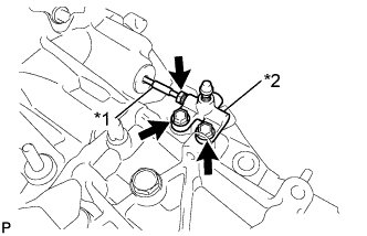
Text in Illustration *1 Bleeder clutch release tube *2 Clutch release bleeder Temporarily tighten the bleeder clutch release tube onto the clutch release bleeder.
-
Temporarily tighten the 2 bolts and install the clutch release bleeder.
-
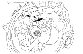
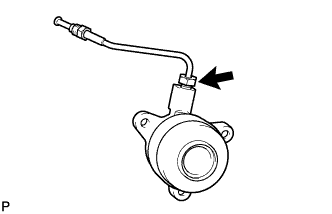
Using a union nut wrench 10 mm, install the bleeder clutch release tube onto the clutch release with bearing cylinder assembly.
- Torque:
- 15 N*m { 155 kgf*cm, 11 ft.*lbf }
Note
Use the formula to calculate special torque values for situations when union nut wrench is combined with a torque wrench Click here.
-
-
REMOVE CLUTCH RELEASE BLEEDER SUB-ASSEMBLY
-
Separate the bleeder clutch release tube from the clutch release bleeder.
-
Remove the 2 bolts and the clutch release bleeder.
-
-
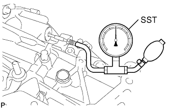
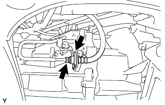
INSPECT CLUTCH PIPE LINE
-
Using SST, apply pressure of 0.1 MPa to the clutch pipe location shown in the illustration and confirm that pressure is maintained for 15 seconds or more.
- SST
- 09992-00242
If the pressure drops, replace the bleeder clutch release tube.
-
-
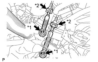
INSTALL CLUTCH RELEASE BLEEDER SUB-ASSEMBLY
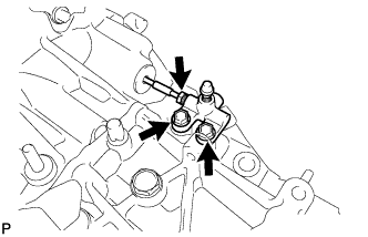
Text in Illustration *1 Bleeder clutch release tube *2 Clutch release bleeder
-
Temporarily tighten the bleeder clutch release tube onto the clutch release bleeder.
-
Install the 2 bolts and clutch release bleeder.
- Torque:
- 17 N*m { 170 kgf*cm, 12 ft.*lbf }
-
Using a union nut wrench 10 mm, install the bleeder clutch release tube.
- Torque:
- 15 N*m { 155 kgf*cm, 11 ft.*lbf }
Note
Use the formula to calculate special torque values for situations when union nut wrench is combined with a torque wrench Click here.
-
-
INSTALL BLEEDER TO ACCUMULATOR TUBE
-
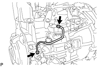
Using a union nut wrench 10 mm, install the bleeder to accumulator tube.
- Torque:
- 15 N*m { 155 kgf*cm, 11 ft.*lbf }
Note
Use the formula to calculate special torque values for situations when union nut wrench is combined with a torque wrench Click here.
-
-
INSTALL MANUAL TRANSAXLE ASSEMBLY
-
Make sure that the knock pins are not loose, bent, damaged or scratched and then install the transaxle onto the engine with the contact surfaces of the engine and transaxle flat against each other.
-
Align the input shaft with the clutch disc and install the manual transaxle onto the engine.
-
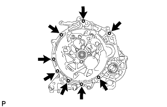
Install the 8 bolts.
- Torque:
- for Flange Bolt
- 37 N*m { 377 kgf*cm, 27 ft.*lbf }
- for Bolt with Washer
- 33 N*m { 337 kgf*cm, 24 ft.*lbf }
Note
Insert knock pins into the knock pin holes securely so that the end face of the transaxle assembly fits close against the engine assembly before tightening the bolts.
-
-
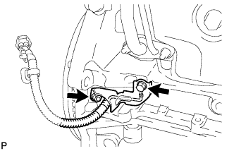
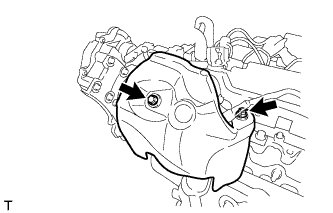
INSTALL CRANKSHAFT POSITION SENSOR
-
Install the crankshaft position sensor and the No. 1 cylinder block insulator with the bolt and nut.
- Torque:
- 7.0 N*m { 71 kgf*cm, 62 in.*lbf }
-
-
INSTALL EXHAUST MANIFOLD CONVERTER SUB-ASSEMBLY
-
Install a new gasket to the turbocharger.
-
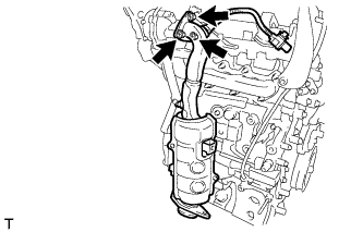
Install the exhaust manifold converter with 3 new nuts.
- Torque:
- 26 N*m { 265 kgf*cm, 19 ft.*lbf }
-
-
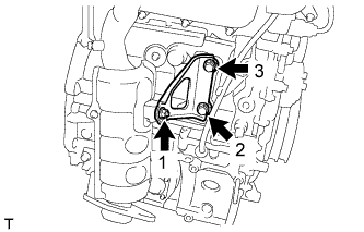
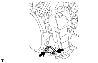
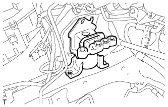
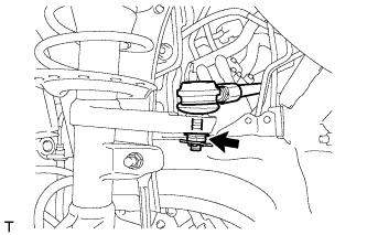
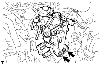
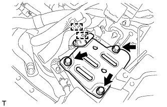
INSTALL MANIFOLD SUPPORT BRACKET
-
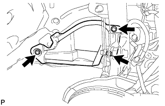
Temporarily tighten the manifold support bracket with the 2 bolts and nut.
-
Fully tighten the 2 bolts and nut, as shown in the illustration.
- Torque:
- 37 N*m { 377 kgf*cm, 27 ft.*lbf }
-
-
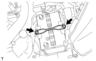
INSTALL NO. 2 MANIFOLD SUPPORT BRACKET
-
Install the No. 2 manifold support bracket with the bolt and nut.
- Torque:
- 37 N*m { 377 kgf*cm, 27 ft.*lbf }
-
-
INSTALL NO. 2 TURBO INSULATOR
-
Install the No. 2 turbo insulator with the bolt and nut.
- Torque:
- 7.0 N*m { 71 kgf*cm, 62 in.*lbf }
-
-
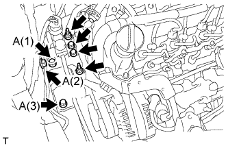
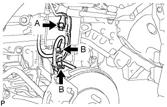
INSTALL ENGINE WIRE
-
Install the engine wire to the engine.
- Torque:
- Generator terminal B nut
- 9.8 N*m { 100 kgf*cm, 87 in.*lbf }
-
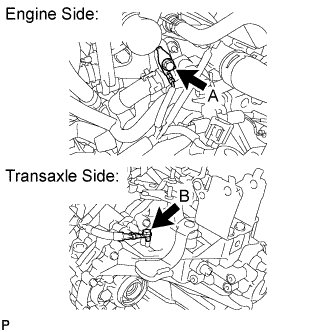
Install the 2 ground bolts.
- Torque:
- Bolt A
- 8.4 N*m { 85 kgf*cm, 74 in.*lbf }
- Bolt B
- 26 N*m { 260 kgf*cm, 19 ft.*lbf }
-
-
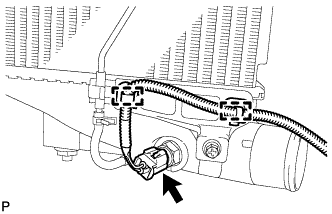
INSTALL STARTER ASSEMBLY
-
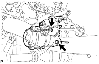
Install the starter assembly with the 2 bolts.
- Torque:
- 37 N*m { 377 kgf*cm, 27 ft.*lbf }
-
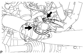
Connect the terminal 30 with the nut.
- Torque:
- 9.8 N*m { 100 kgf*cm, 87 in.*lbf }
-
Connect the connector.
-
Close the terminal cap.
-
-
INSTALL NO. 3 AIR HOSE
-
Install the No. 3 air hose.
-
-
INSTALL NO. 2 RADIATOR HOSE
-
Install the No. 2 radiator hose.
-
-
INSTALL NO. 5 WATER BY-PASS HOSE
-
Install the No. 5 water by-pass hose.
-
-
INSTALL NO. 1 AIR HOSE
-
Install the No. 1 air hose.
-
-
INSTALL COOLER COMPRESSOR ASSEMBLY (w/ Air Conditioning System)
-
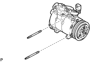
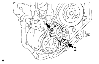
Using a "TORX" socket wrench (E8), install the compressor with the 2 stud bolts.
- Torque:
- 15 N*m { 153 kgf*cm, 11 ft.*lbf }
-
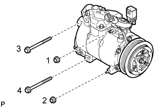
Install the compressor with the 2 bolts and the 2 nuts.
- Torque:
- 25 N*m { 250 kgf*cm, 18 ft.*lbf }
Tech Tips
Tighten the bolts and the nuts in the order shown in the illustration.
-
Connect the connector.
-
-
INSTALL ENGINE MOUNTING INSULATOR LH
Tech Tips
Only perform this procedure when replacement of the engine mounting insulator LH is necessary.
-
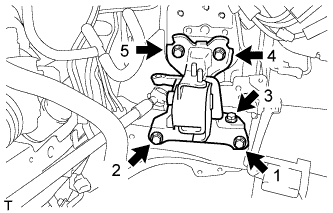
Temporarily tighten the engine mounting insulator with the 5 bolts.
-
Fully tighten the 5 bolts, as shown in the illustration.
- Torque:
- 52 N*m { 530 kgf*cm, 38 in.*lbf }
-
-
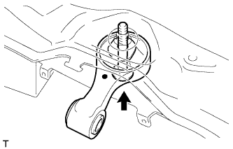
SET ENGINE MOUNTING INSULATOR RH
-
Set the engine mounting insulator RH.
-
-
INSTALL ENGINE ASSEMBLY WITH TRANSAXLE
-
Remove the 2 bolts and 2 engine hangers.
-
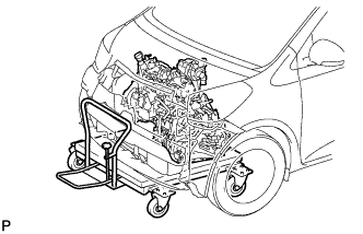
Set the engine assembly with transaxle on the engine lifter.
-
Operate the engine lifter and lift the engine assembly with transaxle to position where the engine mounting insulators RH and LH can be installed.
-
Install the engine mounting insulator LH with the through bolt and nut.
- Torque:
- 52 N*m { 530 kgf*cm, 38 in.*lbf }
-
Temporarily tighten the engine mounting insulator with the 5 bolts and 2 nuts.
-
Fully tighten the 3 bolts to the body, as shown in the illustration.
- Torque:
- Bolt A
- 52 N*m { 530 kgf*cm, 38 ft.*lbf }
-
Fully tighten the 2 bolts and 2 nuts to the engine.
- Torque:
- 52 N*m { 530 kgf*cm, 38 in.*lbf }
-
-
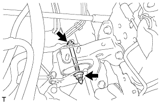
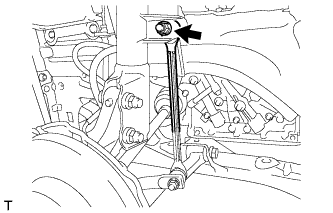
INSTALL ENGINE MOVING CONTROL ROD
Tech Tips
Only perform this procedure when replacement of the engine moving control rod is necessary.
-
Install the engine moving control rod with the bolt.
- Torque:
- 100 N*m { 1020 kgf*cm, 74 ft.*lbf }
-
-
INSTALL ENGINE MOVING CONTROL ROD COVER (for Cold Area)
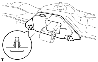
Tech Tips
Only perform this procedure when replacement of the engine moving control rod is necessary.
-
Engage the 2 clips and Install the engine moving control rod cover.
-
-
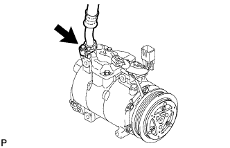
CONNECT SUCTION HOSE SUB-ASSEMBLY (w/ Air Conditioning System)
-
Remove the attached vinyl tape from the suction hose.
-
Sufficiently apply compressor oil to a new O-ring and the fitting surface of the cooler compressor.
Compressor oil ND-OIL 8 or equivalent -
Install the O-ring onto the suction hose.
-
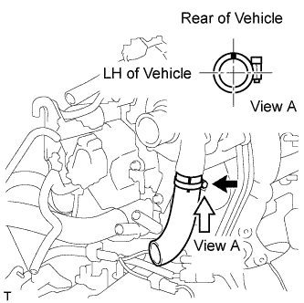
Connect the suction hose to the cooler compressor with the bolt.
- Torque:
- 9.8 N*m { 100 kgf*cm, 87 in.*lbf }
-
-
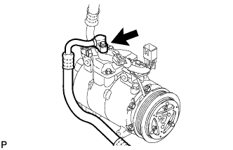
CONNECT DISCHARGE HOSE SUB-ASSEMBLY (w/ Air Conditioning System)
-
Remove the attached vinyl tape from the discharge hose.
-
Sufficiently apply compressor oil to a new O-ring and the fitting surface of the cooler compressor.
Compressor oil ND-OIL 8 or equivalent -
Install the O-ring onto the discharge hose.
-
Connect the discharge hose to the cooler compressor with the bolt.
- Torque:
- 9.8 N*m { 100 kgf*cm, 87 in.*lbf }
-
-
INSTALL FRONT FRAME ASSEMBLY
-
Support the front frame assembly with 4 wooden blocks and the jack.
-
Provisionally install the front frame assembly onto the body with the 6 bolts.
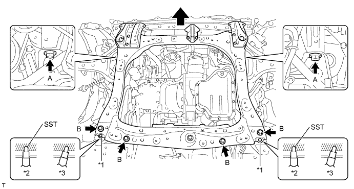
Text in Illustration *1 Datum Hole *2 OK *3 NG Bolt Underhead Length (mm) A 38 B 69 -
By inserting SST into the datum holes in the front frame assembly RH and LH alternately, tighten bolts A and B on both sides to the specified torque, in several steps.
- SST
- 09670-00011
- Torque:
- 108 N*m { 1101 kgf*cm, 80 ft.*lbf, for bolt A }
- 120 N*m { 1224 kgf*cm, 89 ft.*lbf, for bolt B }
Note
-
Insert SST into the datum hole in a vertical orientation.
-
If SST can not be inserted into the datum hole vertically, loosen all the bolts and then insert SST again.
-
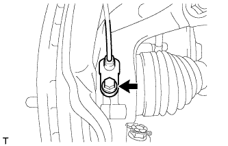
Install the engine moving control rod to engine mounting control bracket with the bolt.
- Torque:
- 120 N*m { 1224 kgf*cm, 89 ft.*lbf }
-
Remove the strong rope from engine mounting control bracket and body.
-
-
INSTALL FRONT DRIVE SHAFT ASSEMBLY LH
-
Coat the spline of the inboard joint with gear oil.
-
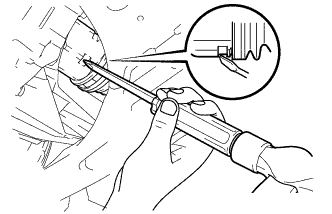
Align the inboard joint splines and install the drive shaft with a screwdriver and hammer.
Note
-
Face the gap of the front drive shaft hole snap ring downward.
-
Do not damage the oil seal.
-
Do not damage the inboard joint boot.
Tech Tips
Confirm whether the drive shaft is securely driven in by checking the reaction force and sound.
-
-
-
INSTALL FRONT DRIVE SHAFT ASSEMBLY RH
Tech Tips
Use the same procedure for the RH side as for the LH side.
-
INSTALL FRONT AXLE ASSEMBLY LH
-
Push the front axle out of the vehicle to align the splines of the drive shaft with the front axle and insert the front axle.
Note
-
Do not push the front axle further out of the vehicle than is necessary.
-
Do not damage the outboard joint boot.
-
Check for any foreign matter on the speed sensor rotor and insertion area.
-
Do not damage the speed sensor rotor.
-
-
-
INSTALL FRONT AXLE ASSEMBLY RH
Tech Tips
Perform the same procedure as above on the opposite side.
-
INSTALL FRONT LOWER SUSPENSION ARM SUB-ASSEMBLY LH
-
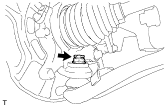
Install the lower arm onto the steering knuckle with a new castle nut.
- Torque:
- 98 N*m { 999 kgf*cm, 72 ft.*lbf }
Note
If the holes for the clip are not aligned, tighten the nut by a further turn of up to 60°.
-
Install a new clip.
-
-
INSTALL FRONT LOWER SUSPENSION ARM SUB-ASSEMBLY RH
Tech Tips
Perform the same procedure as above on the opposite side.
-
INSTALL TIE ROD END SUB-ASSEMBLY LH
-
Install the tie rod end onto the steering knuckle with a new castle nut.
- Torque:
- 59 N*m { 600 kgf*cm, 43 ft.*lbf }
Note
If the holes for the clip are not aligned, tighten the nut by a further turn of up to 60°.
-
Install a new clip.
-
-
INSTALL TIE ROD END SUB-ASSEMBLY RH
Tech Tips
Perform the same procedure as above on the opposite side.
-
INSTALL FRONT STABILIZER LINK ASSEMBLY LH
-
Install the stabilizer link with the nut.
- Torque:
- 74 N*m { 755 kgf*cm, 55 ft.*lbf }
Tech Tips
If the ball joint turns together with the nut, use a socket hexagon wrench 6 to hold the stud.
-
-
INSTALL FRONT STABILIZER LINK ASSEMBLY RH
Tech Tips
Perform the same procedure as above on the opposite side.
-
INSTALL FRONT SPEED SENSOR
-
Install the speed sensor onto the steering knuckle with the bolt.
- Torque:
- 8.5 N*m { 87 kgf*cm, 75 in.*lbf }
Note
-
Check that the speed sensor tip and installation area are free of foreign matter.
-
Install the speed sensor without turning it from its original installation angle.
-
Install the flexible hose and speed sensor with the bolt.
- Torque:
- Bolt A
- 29 N*m { 296 kgf*cm, 21 ft.*lbf }
- Bolt B
- 29 N*m { 300 kgf*cm, 22 ft.*lbf }
Note
Install the flexible hose and speed sensor without twisting them.
-
-
INSTALL FRONT AXLE HUB NUT LH
-
Clean the threaded parts on the drive shaft and axle hub nut using a non-residue solvent.
Note
-
Be sure to perform this work for a new drive shaft.
-
Keep the threaded part free of oil and foreign objects.
-
-
Using a 30 mm deep socket wrench, install a new axle hub nut.
- Torque:
- 216 N*m { 2203 kgf*cm, 159 ft.*lbf }
-
Using a chisel and hammer, stake the axle hub nut.
-
-
INSTALL FRONT AXLE HUB NUT RH
Tech Tips
Perform the same procedure as above on the opposite side.
-
INSTALL TAIL EXHAUST PIPE ASSEMBLY
-
Install the tail exhaust pipe assembly Click here.
-
-
INSTALL CLUTCH HOSE
-
Install a new clip.
-
Using a union nut wrench 10 mm, connect the clutch hose to the clutch release cylinder to flexible hose tube.
- Torque:
- 15 N*m { 155 kgf*cm, 11 ft.*lbf }
Note
Use the formula to calculate special torque values for situations where union nut wrench is combined with a torque wrench Click here.
-
-
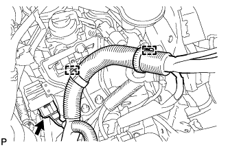
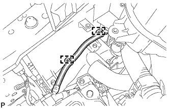
CONNECT TRANSMISSION CONTROL CABLE ASSEMBLY
-
Connect the transmission control cable with the 2 clips*1 onto the transaxle.
-
Install the 2 new clips*2 onto the transmission control cable.
-
-
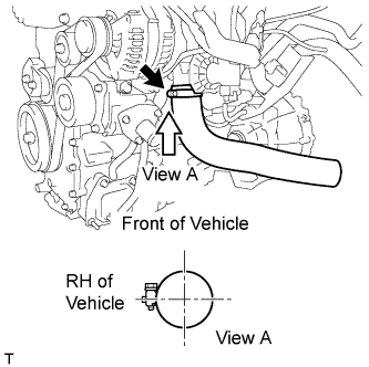
INSTALL NO. 1 AIR TUBE
Text in Illustration *1 Paint Mark
-
Install the No. 1 air tube with the nut.
- Torque:
- 7.0 N*m { 71 kgf*cm, 62 in.*lbf }
-
Connect the No. 1 air hose.
Note
Align the air hose paint mark with the air tube paint mark.
-
-
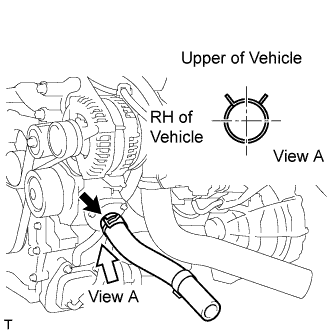
INSTALL NO. 2 AIR HOSE
Text in Illustration *1 Paint Mark
-
Install the No. 2 air hose.
Note
Align the air hose paint mark with the air tube paint mark.
-
-
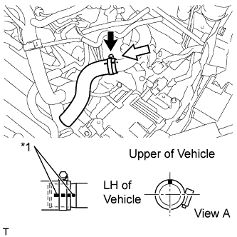
INSTALL NO. 1 RADIATOR HOSE
-
Install the No. 1 radiator hose.
-
-
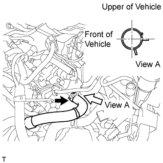
CONNECT OUTLET HEATER WATER HOSE
-
Connect the outlet heater water hose.
-
-
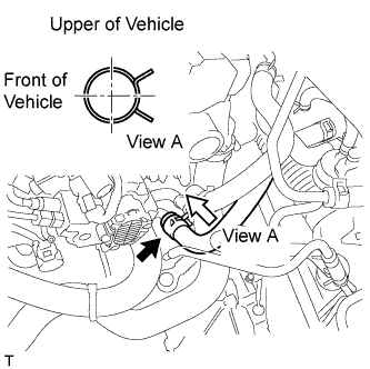
CONNECT INLET HEATER WATER HOSE
-
Connect the inlet heater water hose.
-
-
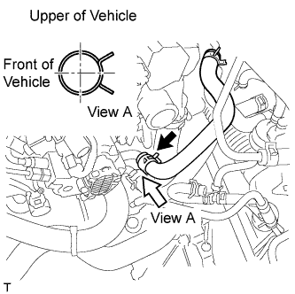
CONNECT UNION TO CONNECTOR TUBE HOSE
-
Connect the union to connector tube hose.
-
-
INSTALL FAN AND GENERATOR V BELT
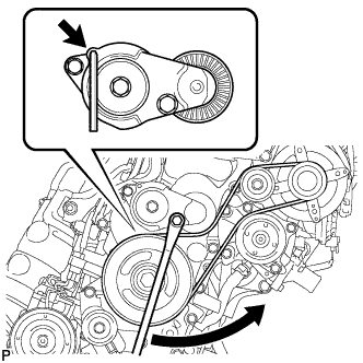
-
Install the V-ribbed belt.
-
Turn the V-ribbed belt tensioner counterclockwise and remove the 5 mm bi-hexagon wrench.
-
-
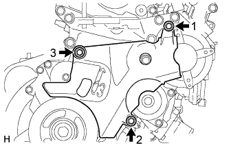
INSTALL NO. 2 IDLE PULLEY ASSEMBLY (w/ Air Conditioning System)
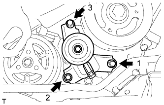
-
Temporarily tighten the No. 2 idle pulley with the 3 bolts.
-
Fully tighten the 3 bolts, as shown in the illustration.
- Torque:
- 25 N*m { 250 kgf*cm, 18 ft.*lbf }
-
-
INSTALL NO. 1 V (COOLER COMPRESSOR TO CRANKSHAFT PULLEY) BELT (w/ Air Conditioning System)
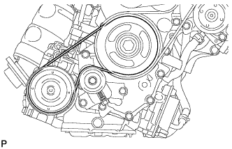
-
Temporarily install the No. 1 V belt onto each pulley.
Note
-
Before installing the V belt, check each pulley for any liquid or chips.
-
Check that the ribs of the V belt are correctly fitted into the grooves of the pulleys.
-
-
-
ADJUST NO. 1 V (COOLER COMPRESSOR TO CRANKSHAFT PULLEY) BELT (w/ Air Conditioning System)
-
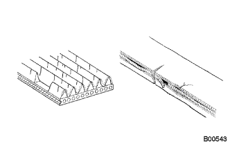
Check the belt for wear, cracks or other signs of damage.
If any of the following defects is found, replace the V belt.
Tech Tips
-
The belt is cracked.
-
The belt is worn out to the extent that the cords are exposed.
-
The belt has chunks missing from the ribs.
-
-
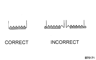
Check that the belt fits properly in the ribbed grooves.
Tech Tips
Check with your hand to confirm that the belt has not slipped out of the grooves on the bottom to the pulley. If it has slipped out, replace the V belt. Install a new V belt correctly.
-
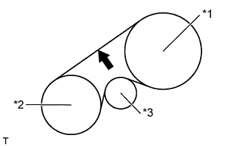
Text in Illustration *1 Crankshaft *2 A/C Compressor *3 Tensioner Inspect the No. 1 V belt deflection.
Deflection Pressing Force
N ( kg, lb)
New Belt
mm (in.)
Used Belt
mm (in.)
10
(10, 22)
8.0 to 10.0
(0.315 to 0.394)
10.0 to 12.0
(0.394 to 0.472)
Tech Tips
No. 1 V belt tension
New Belt
N (kg, lb)
Used Belt
N (kg, lb)
397 to 593
(40 to 60, 89 to 133)
300 to 398
(31 to 41, 67 to 89)
Note
-
Check the No. 1 V belt deflection at the specified point.
-
When installing a new belt, set its deflection value as specified.
-
When checking a belt used for over 5 minutes, confirm that the deflection value is within the specified range for a used belt.
-
When reinstalling a belt used for over 5 minutes, check whether its deflection value is within the specified range for a used belt.
-
-
-
INSPECT NO. 1 V (COOLER COMPRESSOR TO CRANKSHAFT PULLEY) BELT (w/ Air Conditioning System)
-
Check the belt for wear, cracks or other signs of damage.
If any of the following defects is found, replace the V belt.
Tech Tips
-
The belt is cracked.
-
The belt is worn out to the extent that the cords are exposed.
-
The belt has chunks missing from the ribs.
-
-
Check that the belt fits properly in the ribbed grooves.
Tech Tips
Check with your hand to confirm that the belt has not slipped out of the grooves on the bottom to the pulley. If it has slipped out, replace the V belt. Install a new V belt correctly.
-
Text in Illustration *1 Crankshaft *2 A/C Compressor *3 Tensioner Inspect the No. 1 V belt deflection.
Deflection Pressing Force
N ( kg, lb)
New Belt
mm (in.)
Used Belt
mm (in.)
10
(10, 22)
8.0 to 10.0
(0.315 to 0.394)
10.0 to 12.0
(0.394 to 0.472)
Tech Tips
No. 1 V belt tension
New Belt
N (kg, lb)
Used Belt
N (kg, lb)
397 to 593
(40 to 60, 89 to 133)
300 to 398
(31 to 41, 67 to 89)
Note
-
Check the No. 1 V belt deflection at the specified point.
-
When installing a new belt, set its deflection value as specified.
-
When checking a belt used for over 5 minutes, confirm that the deflection value is within the specified range for a used belt.
-
When reinstalling a belt used for over 5 minutes, check whether its deflection value is within the specified range for a used belt.
-
-
-
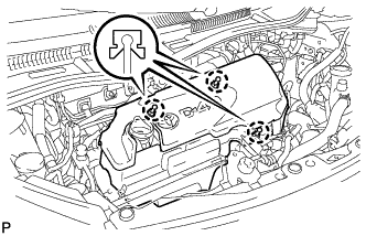
INSTALL NO. 4 ENGINE COVER (w/ No. 4 Engine Cover)
-
Temporarily install the No. 4 engine cover with the 2 bolts and nut.
-
Fully tighten the 2 bolts and nut in the order shown in the illustration.
- Torque:
- 10 N*m { 102 kgf*cm, 7 ft.*lbf }
-
-
INSTALL NO. 1 COOLER COVER (w/ No. 1 Cooler Cover)
-
Temporarily install the No. 1 cooler cover with the 2 nuts.
-
Fully tighten the 2 nuts in the order shown in the illustration.
- Torque:
- 9.8 N*m { 100 kgf*cm, 87 in.*lbf }
-
-
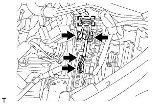
CONNECT ENGINE WIRE
-
Connect the engine wire from the engine room junction block.
-
Connect the 4 engine wire connectors and clamp.
-
Install the junction block cover.
-
-
Install the engine ground bolt.
- Torque:
- 8.4 N*m { 85 kgf*cm, 74 in.*lbf }
-
Connect the 3 engine wire connectors to the battery terminal.
-
-
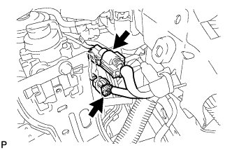
CONNECT NO. 2 FUEL HOSE
-
Connect the No. 2 fuel hose.
-
-
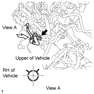
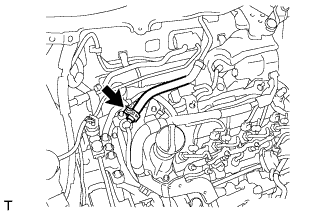
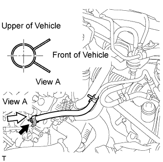
INSTALL INJECTION PUMP TO FUEL FILTER FUEL HOSE
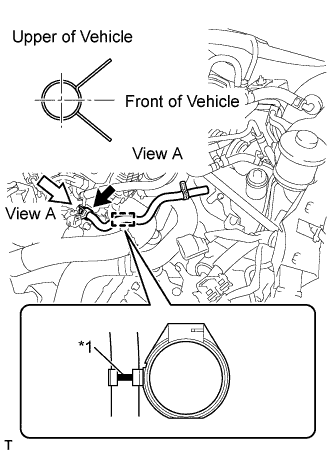
Text in Illustration *1 Paint Mark
-
Engage the hose clamp and install the injection pump to fuel filter fuel hose.
Note
Align the fuel hose paint mark with the clamp center.
-
-
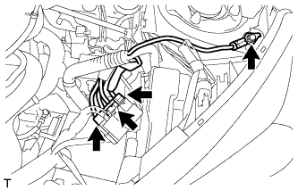
INSTALL FUEL FILTER ASSEMBLY
-
Install the fuel filter with the 2 nuts.
- Torque:
- 19 N*m { 189 kgf*cm, 14 ft.*lbf }
-
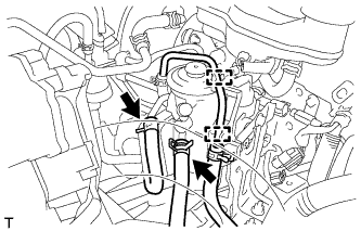
Connect the 2 fuel hose clamps to the fuel filter.
-
Connect the 2 fuel hoses to the fuel filter.
-
Connect the 2 connectors.
-
Connect the 2 wire harness clamps.
-
Connect the connector.
-
-
INSTALL NO. 2 BATTERY CARRIER
-
Install the No. 2 battery carrier with the 3 bolts.
- Torque:
- 17 N*m { 175 kgf*cm, 13 ft.*lbf }
-
Connect the 2 wire harness clamps.
-
-
INSTALL BATTERY TRAY
-
INSTALL BATTERY
-
INSTALL BATTERY CLAMP SUB-ASSEMBLY
-
Install the battery clamp with the 2 nuts.
- Torque:
- 3.5 N*m { 36 kgf*cm, 31 in.*lbf }
-
-
INSTALL AIR CLEANER HOSE ASSEMBLY
Text in Illustration *1 Paint Mark
-
Install the air cleaner hose.
Note
Position the clip so that the claws are centered over the paint mark on the hose.
-
-
INSTALL ENGINE COVER ASSEMBLY
-
Engage the 3 claws and install the engine cover.
-
-
INSTALL COWL PANEL SUB-ASSEMBLY
-
Install the cowl panel sub-assembly Click here.
-
-
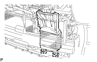
INSTALL INTERCOOLER ASSEMBLY
-
Install the intercooler with the intercooler cooling air duct.
-
Engage the 2 wire harness clamps.
-
Connect the intake air temperature sensor connector.
-
Connect the vacuum transmitting hose.
-
Engage the 2 wire harness clamps and install the wire harness to the intercooler cooling air duct.
-
-
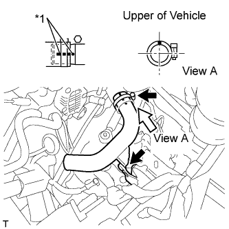
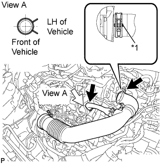
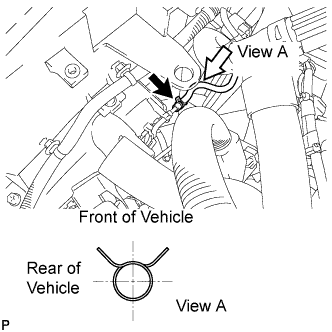
CONNECT NO. 3 AIR HOSE
-
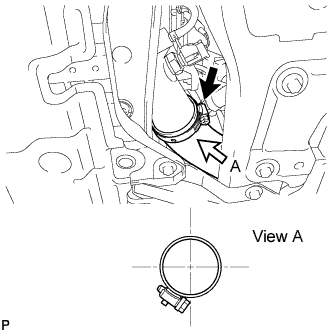
Connect the No. 3 air hose and tighten the hose clamp.
Tech Tips
Install the clip as shown in the illustration.
-
-
CONNECT NO. 2 AIR HOSE
-
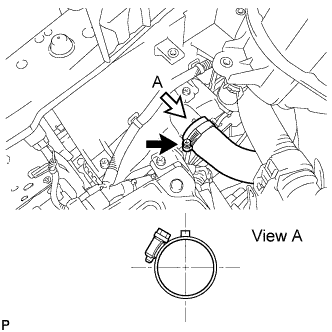
Connect the No. 2 air hose and tighten the hose clamp.
Tech Tips
Install the clip as shown in the illustration.
-
-
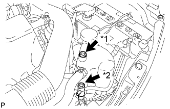
INSTALL RADIATOR RESERVE TANK ASSEMBLY
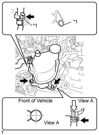
Text in Illustration *1 Protrusion
-
Connect the No. 5 water by-pass hose.
-
Connect the air bleed valve.
Note
Install the air bleed valve with the protrusion facing the opening of the reserve tank.
-
Install the radiator reserve tank with the 2 bolts.
- Torque:
- 7.5 N*m { 76 kgf*cm, 66 ft.*lbf }
-
-
INSTALL RADIATOR ASSEMBLY
-
Install the radiator assembly Click here.
-
-
ADD MANUAL TRANSAXLE OIL
-
Install a new gasket and the manual transmission drain plug.
- Torque:
- 45 N*m { 459 kgf*cm, 33 ft.*lbf }
-
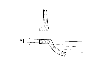
Text in Illustration *1 0 to 5 mm (0 to 0.20 in.) Add manual transaxle oil.
-
-
FILL BRAKE FLUID RESERVOIR WITH BRAKE FLUID
-
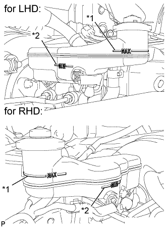
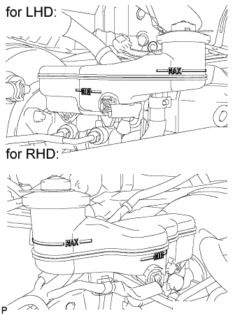
Text in Illustration *1 MAX Line *2 MIN Line Fill the reservoir with brake fluid.
Brake Fluid SAE J1703 or FMVSS No. 116 DOT 3 Note
Add brake fluid to keep the level between the MIN and MAX lines of the reservoir while bleeding the brakes.
-
-
BLEED CLUTCH LINE
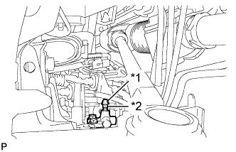
Text in Illustration *1 Bleeder plug cap *2 Bleeder plug Tech Tips
In case of clutch fluid replacement, make sure that the old fluid is replaced in the clutch line between the reservoir and the bleeder before bleeding.
-
Remove the bleeder plug cap.
-
Connect a vinyl tube to the bleeder plug.
-
Depress the clutch pedal 5 times, and then loosen the bleeder plug while the pedal is depressed.
-
When fluid no longer comes out, tighten the bleeder plug, and then release the clutch pedal.
-
Repeat both of the previous 2 steps 6 times.
-
Tighten the bleeder plug.
- Torque:
- 8.4 N*m { 86 kgf*cm, 74 in.*lbf }
-
Depress the clutch pedal 10 times or more and confirm its operation.
Note
This must be performed before the engine is started.
-
Install the bleeder plug cap.
-
Check that all the air has been bled from the clutch line.
-
-
CHECK BRAKE FLUID LEVEL
-
Check the brake fluid level.
If brake fluid level is lower than the MIN line, check for leaks and inspect the disc brake pads. If necessary, refill the reservoir with brake fluid to the MAX line after repair or replacement.
Brake Fluid SAE J1703 or FMVSS No. 116 DOT 3
-
-
ADD ENGINE OIL
-
Add clean engine oil and install the oil filler cap.
Engine Oil Engine Oil Grade Oil Viscosity (SAE) w/o DPF ACEA C2, B1, API CF-4 or CF
(You may also use API CE or CD)
-
0W-30
-
5W-30
-
10W-30
-
15W-40
-
20W-50
w/ DPF ACEA C2
-
0W-30
-
5W-30
Capacity Item Capacity Drain and refill with oil filter change 4.0 liters (4.2 US qts, 3.5 Imp. qts) Drain and refill with out oil filter change 3.6 liters (3.8 US qts, 3.2 Imp. qts) Dry fill 4.8 liters (5.1 US qts, 4.2 Imp. qts) -
-
-
ADD ENGINE COOLANT (w/o Combustion Type Power Heater)
-
Tighten the radiator drain cock plug.
-
Text in Illustration *1 Air Bleed Valve 1 *2 Air Bleed Valve 2 Loosen the air bleed valve 1 and the air bleed valve 2.
-
Add TOYOTA Super Long Life Coolant (SLLC).
Standard Capacity Item Capacity w/o Combustion Type Power Heater 4.5 liters (4.8 US qts, 4.0 Imp. qts) Note
Never use water as a substitute for engine coolant.
Tech Tips
TOYOTA vehicles are filled with TOYOTA SLLC at the factory. In order to avoid damage to the engine cooling system and other technical problems, only use TOYOTA SLLC or similar high quality ethylene glycol based non-silicate, non-amine, non-nitrite, non-borate coolant with long-life hybrid organic acid technology (coolant with long-life hybrid organic acid technology is a combination of low phosphates and organic acids).
-
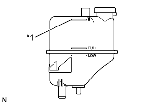
Text in Illustration *1 B Line Add coolant to the B line of the radiator reserve tank.
-
Squeeze the inlet and outlet radiator hoses several times by hand, and then check the level of the coolant.
If the coolant level is low, add coolant.
-
Text in Illustration *1 Air Bleed Valve 1 *2 Air Bleed Valve 2 Tighten the air bleed valve 1 and the air bleed valve 2.
-
Install the reserve tank cap sub-assembly.
-
Start the engine and warm it up.
-
Bleed air from the cooling system.
Note
-
Before starting the engine, turn the A/C switch off.
-
Adjust the air conditioning temperature setting to MAX (HOT).
-
Adjust the air conditioning blower setting to LO.
-
Warm up the engine until the thermostat opens. While the thermostat is open, allow the coolant to circulate for several minutes.
Tech Tips
Thermostat opening timing can be determined by squeezing the inlet radiator hose, and sensing vibrations when the engine coolant starts to flow inside the hose.
CAUTION:
When squeezing the radiator hoses:
-
Wear protective gloves.
-
Be careful as the radiator hoses are hot.
-
Keep your hands away from the radiator fan.
-
-
-
Stop the engine, and wait until the engine coolant cools down.
-
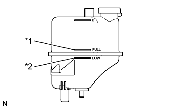
Text in Illustration *1 FULL Line *2 LOW Line After the engine has cooled down, check that the coolant level is between the FULL and LOW lines.
If the coolant level is low, add coolant to the reservoir tank FULL line.
-
-
ADD ENGINE COOLANT (w/ Combustion Type Power Heater)
-
Tighten the radiator drain cock plug.
-
Text in Illustration *1 Air Bleed Valve 1 *2 Air Bleed Valve 2 Loosen the air bleed valve 1 and the air bleed valve 2.
-
Add TOYOTA Super Long Life Coolant (SLLC).
Standard Capacity Item Capacity w/ Combustion Type Power Heater 4.9 liters (5.2 US qts, 4.3 Imp. qts) Note
Never use water as a substitute for engine coolant.
Tech Tips
TOYOTA vehicles are filled with TOYOTA SLLC at the factory. In order to avoid damage to the engine cooling system and other technical problems, only use TOYOTA SLLC or similar high quality ethylene glycol based non-silicate, non-amine, non-nitrite, non-borate coolant with long-life hybrid organic acid technology (coolant with long-life hybrid organic acid technology is a combination of low phosphates and organic acids).
-
Text in Illustration *1 B Line Add coolant to B line of the radiator reserve tank.
-
Squeeze the inlet and outlet radiator hoses several times by hand, and then check the level of the coolant.
If the coolant level is low, add coolant.
-
Text in Illustration *1 Air Bleed Valve 1 *2 Air Bleed Valve 2 Tighten the air bleed valve 1 and the air bleed valve 2.
-
Start the engine, maintain the speed at 3000 rpm for 10 seconds, and idle the engine for 10 seconds. Repeat the same procedure above 4 more times.
-
Install the reserve tank cap sub-assembly.
-
Loosen the air bleed valve 1 and the air bleed valve 2.
-
Add 350 cc (21.3 cu in.) coolant.
-
Tighten the air bleed valve 1 and the air bleed valve 2.
-
Start the engine and warm it up.
-
Bleed air from the cooling system.
Note
-
Before starting the engine, turn the A/C switch off.
-
Adjust the air conditioning temperature setting to MAX (HOT).
-
Adjust the air conditioning blower setting to LO.
-
Warm up the engine until the thermostat opens. While the thermostat is open, allow the coolant to circulate for several minutes.
Tech Tips
Thermostat opening timing can be determined by squeezing the inlet radiator hose, and sensing vibrations when the engine coolant starts to flow inside the hose.
CAUTION:
When squeezing the radiator hoses:
-
Wear protective gloves.
-
Be careful as the radiator hoses are hot.
-
Keep your hands away from the radiator fan.
-
-
-
Stop the engine, and wait until the engine coolant cools down.
-
Text in Illustration *1 FULL Line *2 LOW Line After the engine has cooled down, check that the coolant level is between the FULL and LOW lines.
If the coolant level is low, add coolant to the reservoir tank FULL line.
-
-
BLEED AIR FROM FUEL SYSTEM
-
INITIALIZATION AND REGISTRATION
-
CHARGE REFRIGERANT (w/ Air Conditioning System)
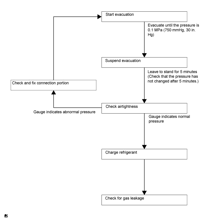
Tech Tips
Charge refrigerant in accordance with the equipment manual.
-
Perform vacuum purging using a vacuum pump.
-
Charge refrigerant HFC-134a (R134a).
- SST
- 09985-20010 ( 09985-02010, 09985-02050, 09985-02060, 09985-02070, 09985-02080, 09985-02090, 09985-02110, 09985-02130, 09985-02140, 09985-02150 )
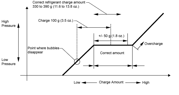
Standard 330 to 390 g (11.6 to 13.8 oz.) Note
-
Do not start the engine before charging it with refrigerant as the cooler compressor does not work properly without sufficient refrigerant. This could cause the compressor to overheat.
-
Approximately 100 g (3.5 oz.) of refrigerant may need to be charged after bubbles disappear.
The volume of refrigerant should be measured, not checked with the sight glass.
Tech Tips
-
The relationship between the refrigerant charge amount and the pressure is as follows.
-
High Charge Range:
If the refrigerant is overcharged, the pressure rises on the high-pressure side. High-pressure cut off frequently occurs. This causes insufficient cooling performance and also insufficient compressor lubrication.
-
Low Charge Range:
A shortage of refrigerant causes insufficient cooling performance and low circulation of refrigerant oil, which shortens the compressor life. Operation with insufficient coolant raises the refrigerant temperature and causes heat deterioration of the rubber seals and hoses. Cracking and subsequent refrigerant leakage may occur.
-
Install the caps onto the service valves on the refrigerant line.
-
-
WARM UP ENGINE (w/ Air Conditioning System)
Note
Warm up the engine at less than 2000 rpm for 1 minute or more after charging it with refrigerant.
-
INSPECT REFRIGERANT LEAK (w/ Air Conditioning System)
-
After recharging the refrigerant gas, check for refrigerant gas leakage using a halogen leak detector.
-
Perform the operation as follows:
-
Stop the engine.
-
Secure good ventilation (the halogen leak detector may react to volatile gases other than refrigerant, such as evaporated gasoline or exhaust gas).
-
Repeat the test 2 or 3 times.
-
Make sure that some refrigerant remains in the refrigeration system.
When the compressor is off: approximately 392 to 588 kPa (4 to 6 kgf/cm2, 57 to 85 psi)
Tech Tips
It is impossible for the above pressure to be maintained if there is leakage.
-
-
Using the halogen leak detector, check the refrigerant line, especially at the connection points, for leakage.
-
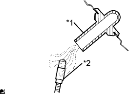
Text in illustration *1 Drain hose *2 Halogen leak detector Bring the halogen leak detector close to the drain hose before performing the test.
Tech Tips
-
After the blower motor has stopped, leave the cooling unit for at least 15 minutes.
-
Place the halogen leak detector sensor under the drain hose.
-
When bringing the halogen leak detector close to the drain hose, make sure that the halogen leak detector does not react to other volatile gases.
If such a reaction is unavoidable, the vehicle must be lifted up.
-
-
If no gas leakage is detected from the drain hose, remove the blower motor from the cooling unit. Insert the halogen leak detector sensor into the unit and perform the test.
-
Disconnect the pressure switch connector and leave it for approximately 20 minutes. Bring the halogen leak detector close to the pressure switch and perform the test.
-
-
INSPECT MANUAL TRANSAXLE OIL LEVEL
-
Text in Illustration *1 0 to 5 mm (0 to 0.20 in.) Check that the oil surface is within 5 mm (0.20 in.) of the bottom of the manual transmission filler plug opening.
Note
Excessively large or small amounts of oil may cause problems.
-
Check for oil leakage when the oil level is low.
-
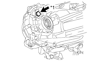
Text in Illustration *1 Filler plug Install the manual transmission filler plug and a new gasket.
- Torque:
- 39 N*m { 400 kgf*cm, 29 ft.*lbf }
-
-
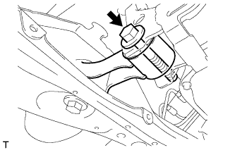
INSPECT FOR OIL LEAK
-
INSPECT FOR COOLANT LEAK
CAUTION:
To avoid the danger of being burned, do not remove the radiator cap sub-assembly while the engine and radiator assembly are still hot. Thermal expansion will cause hot engine coolant and steam to blow out from the radiator assembly.
-
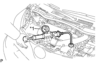
Text in Illustration *1 Radiator Cap Tester Fill the radiator assembly with engine coolant, and attach a radiator cap tester.
-
Pump the tester to 118 kPa (1.2 kgf/cm2, 17.1 psi), and then check that the pressure does not drop.
If the pressure drops, check the hoses, radiator assembly and water pump assembly for leaks. If there are no signs or traces of external engine coolant leaks, check the heater core, cylinder block and head.
-
-
INSPECT FOR FUEL LEAK
-
Connect an intelligent tester to the DLC3.
-
Turn the ignition switch to ON.
-
Turn the tester on.
-
Enter the following menus: Powertrain / Engine / Active Test.
-
Perform the Active Test.
Intelligent Tester Display Test Details Control Range Diagnostic Notes Test the Fuel Leak Pressurize common rail internal fuel pressure, and check for fuel leaks Stop/Start Perform inspection of the high pressure fuel system.
Test is possible when the following conditions are met:
-
Warmed up engine.
-
Vehicle is stopped.
-
Battery voltage is 12 V or more.
-
PM regeneration is not operating.
-
Engine speed is less than 4000 rpm.
Results of real-vehicle check:
-
Engine Speed: 2702 rpm
-
Fuel Pressure: 108570 kPa
-
Target Common Rail Pressure: 105500 kPa
-
Target Pump SCV Current: 1.2 A
-
MAP: 127 kPa
-
MAF: 28 g/sec.
-
-
-
INSPECT FOR EXHAUST GAS LEAK
-
INSPECT FOR OIL LEAK
-
Start the engine. Check for engine oil leaks from the connected parts of the oil filter cap and oil filter drain plug.
-
-
INSTALL FRONT FLOOR COVER RH
-
INSTALL FRONT FLOOR COVER LH
-
INSTALL NO. 3 ENGINE UNDER COVER
-
Install the No. 3 engine under cover with the 3 clips.
-
-
INSTALL ENGINE UNDER COVER
-
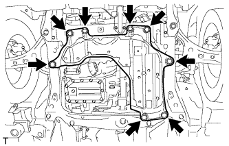
Install the engine under cover with the 4 bolts and 4 clips.
- Torque:
- 5.0 N*m { 51 kgf*cm, 44 in.*lbf }
-
-
INSTALL FRONT WHEELS
- Torque:
- 103 N*m { 1050 kgf*cm, 76 ft.*lbf }
-
ADJUST FRONT WHEEL ALIGNMENT
-
CHECK ABS SPEED SENSOR SIGNAL