CYLINDER HEAD GASKET INSTALLATION

-
INSTALL CYLINDER HEAD GASKET
-
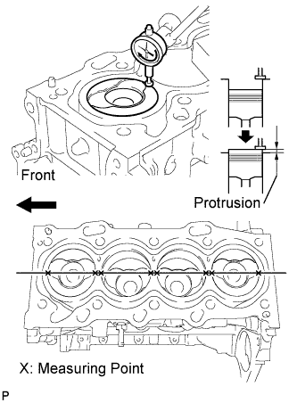
Inspect the protrusion height of the piston heads.
-
Place a dial indicator on the cylinder block as shown in the illustration.
Note
Make sure that the dial indicator is at right angles to the cylinder block top surface.
-
Measure the protrusion height of the piston head of each cylinder at 2 places as shown in the illustration.
-
-
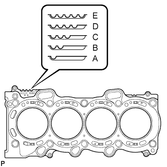
Select a new cylinder head gasket.
-
Select the highest protrusion height among the 8 measurements records. It is used to select a new cylinder head gasket.
Piston Protrusion Piston Protrusion mm (in.) Gasket Cutout Gasket Size 0.525 to 0.575
(0.020 to 0.023)
1 A 0.576 to 0.625
(0.023 to 0.025)
2 B 0.626 to 0.675
(0.025 to 0.027)
3 C 0.676 to 0.725
(0.027 to 0.029)
4 D 0.726 to 0.775
(0.029 to 0.031)
5 E
-
-
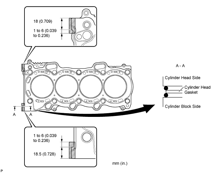
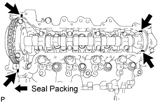
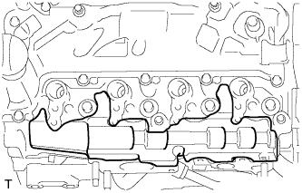
Install the cylinder head gasket.
-
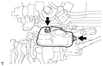
Apply seal packing (Diameter 3.5 to 4.5 mm (0.138 to 0.177 in.)) to the cylinder block side as shown in the illustration.
Seal packing Toyota Genuine Seal Packing Black, Three Bond 1207B or equivalent Note
Remove any oil from the contact surface.
-
Place a new cylinder head gasket on the cylinder block with the Lot No. stamp facing upward.
-
Apply seal packing (Diameter 3.5 to 4.5 mm (0.138 to 0.177 in.)) to the top surface of the cylinder head again as shown in the illustration.
Seal packing Toyota Genuine Seal Packing Black, Three Bond 1207B or equivalent -
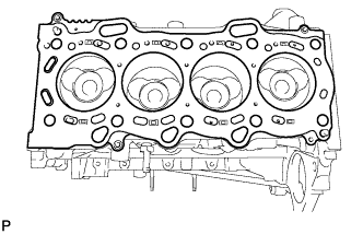
Install the cylinder head gasket onto the cylinder block.
Note
-
Remove any oil from the contact surface.
-
Install the cylinder head within 3 minutes, and tighten the bolts within 15 minutes of applying the seal packing.
-
-
-
-
INSTALL CYLINDER HEAD SUB-ASSEMBLY
Tech Tips
The cylinder head bolts are tightened in multiple steps.
-
Apply a light coat of engine oil to the threads of the cylinder head bolts.
-
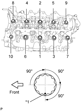
Text in Illustration *1 Paint Mark Using several passes, uniformly install and tighten the 10 cylinder head bolts and plate washers in the sequence shown in the illustration. (*1)
- Torque:
- 50 N*m { 510 kgf*cm, 37 ft.*lbf }
-
Mark the front of the cylinder head bolts with paint.
-
Using the same sequence as step (*1), retighten the cylinder head bolts by an additional 90° repeat it 2 more times.
-
Check that each paint mark is now 270° from the front.
-
-
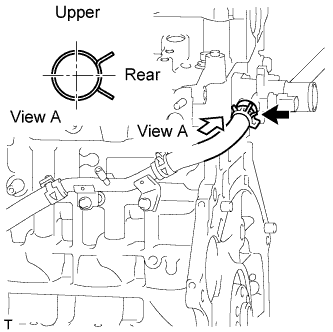
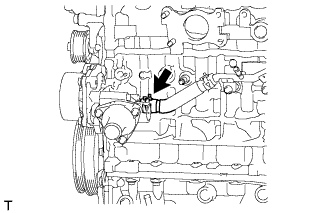
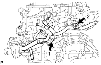
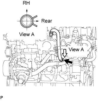
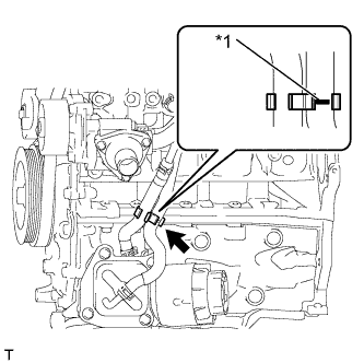
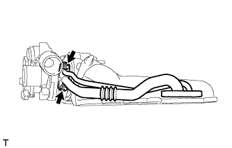
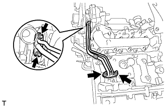
CONNECT WATER INLET HOSE RH
-
Connect the water inlet hose RH.
-
-
INSTALL NO. 1 VALVE ROCKER ARM SUB-ASSEMBLY
-
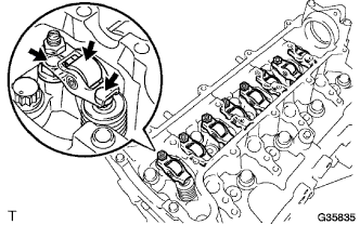
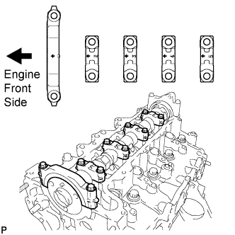
Apply engine oil to the stem end caps, valve rocker arm pivot top surfaces and valve rocker arm roller portions.
-
Install the 8 valve rocker arms.
-
-
INSTALL CAMSHAFT
-
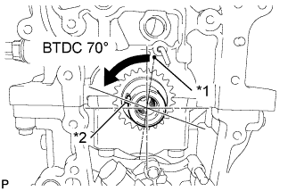
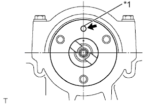
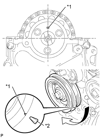
Text in Illustration *1 TDC Mark *2 Key Turn the crankshaft to set the key in the 70° BTDC position.
-
Apply engine oil to the camshaft journal portion and cam portion.
-
Examine the front marks and numbers and check that the sequence is as shown in the illustration. Then, temporarily tighten the camshaft with the camshaft bearing caps and bolts.
Note
Do not tilt the valve rocker arm when installing the camshaft onto the cylinder head.
-
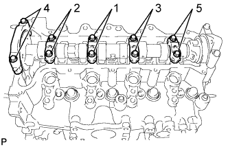
Using several steps, temporarily tighten the bolts in the sequence shown in the illustration, and then tighten the bolts to the specified torque.
- Torque:
- 19 N*m { 194 kgf*cm, 14 ft.*lbf }
-
-
INSTALL CHAIN SUB-ASSEMBLY
-
Text in Illustration *1 Straight Pin Turn the camshaft to set the straight pin in the position shown in the illustration.
-
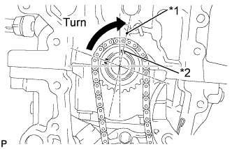
Text in Illustration *1 TDC Mark *2 Key Turn the crankshaft to set the key in the position shown in the illustration.
-
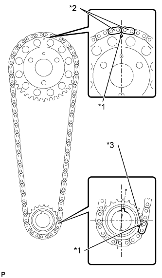
Text in Illustration *1 Timing Mark *2 Orange Mark Plate *3 Yellow Mark Plate Align the chain's 2 orange mark plates with the timing mark on the camshaft timing sprocket, and the yellow mark plate with the timing mark on the crankshaft timing sprocket.
-
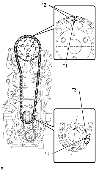
Text in Illustration *1 Timing Mark *2 Orange Mark Plate *3 Yellow Mark Plate Install the chain, camshaft timing sprocket and crankshaft sprocket together onto the engine.
-
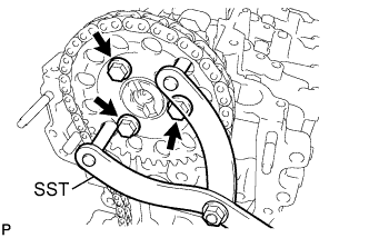
Using SST, fix the camshaft timing sprocket, and install the camshaft timing sprocket with the 3 bolts.
- SST
- 09960-10010 ( 09962-01000, 09963-01000 )
- Torque:
- 20 N*m { 204 kgf*cm, 15 ft.*lbf }
-
-
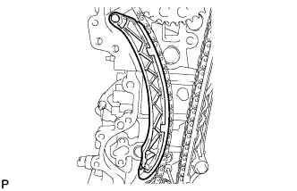
INSTALL NO. 1 CHAIN VIBRATION DAMPER
-
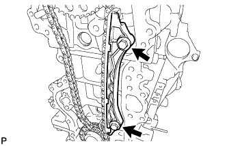
Install the chain vibration damper with the 2 bolts.
- Torque:
- 21 N*m { 214 kgf*cm, 15 ft.*lbf }
-
-
INSTALL CHAIN TENSIONER SLIPPER
-
Install the chain tensioner slipper onto the cylinder block.
-
-
INSTALL NO. 1 CHAIN TENSIONER ASSEMBLY
-
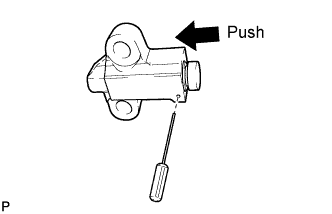
Push in the plunger until the groove is aligned with the tensioner hole, and then insert a 1.1 mm (0.043 in.) diameter bar.
-
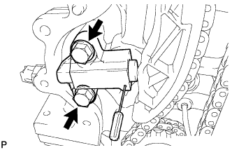
Install the chain tensioner with the 2 bolts.
- Torque:
- 21 N*m { 214 kgf*cm, 15 ft.*lbf }
-
Remove the 1.1 mm (0.043 in.) diameter bar from the chain tensioner.
-
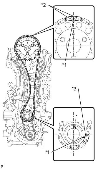
Text in Illustration *1 Timing Mark *2 Orange Mark Plate *3 Yellow Mark Plate Check that the mark plate and timing mark are in the positions shown in the illustration.
-
-
INSTALL TIMING CHAIN COVER SUB-ASSEMBLY
-
Install the No. 2 timing chain cover with the clip.
-
-
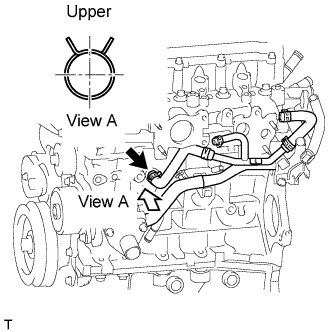
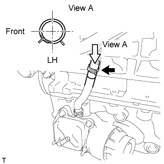
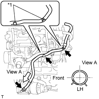
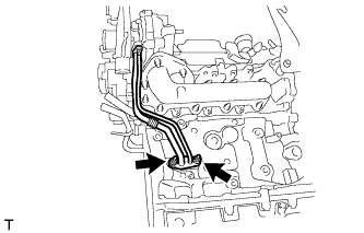
CONNECT WATER INLET HOSE LH
-
Connect the water inlet hose LH.
Tech Tips
The clip at the water inlet housing can be installed in any orientation, as long it does not contact any of the surrounding parts.
-
-
INSTALL CRANKSHAFT DAMPER SUB-ASSEMBLY
-
Align the key with the key groove of the crankshaft damper, and slide the crankshaft damper to the crankshaft.
-
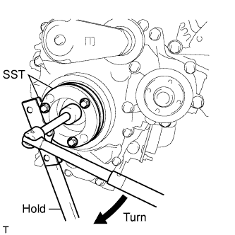
Using SST, secure the crankshaft damper.
- SST
- 09213-58014
- 09330-00021
-
Tighten the bolt to the specified torque.
- Torque:
- 210 N*m { 2141 kgf*cm, 155 ft.*lbf }
-
-
INSTALL NO. 2 TIMING CHAIN COVER
-
Install the No. 2 timing chain cover with the clip.
-
-
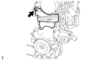
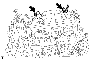
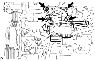
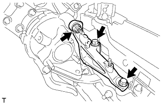
INSTALL ENGINE MOUNTING BRACKET RH
-
Temporarily tighten the engine mounting bracket with the 4 bolts.
-
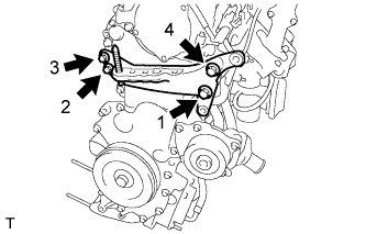
Fully tighten the 4 bolts, as shown in the illustration.
- Torque:
- 55 N*m { 561 kgf*cm, 41 ft.*lbf }
-
-
CHECK VALVE CLEARANCE
-
Text in Illustration *1 Timing Mark *2 TDC Mark Set the No. 1 cylinder to TDC/Compression.
-
Turn the crankshaft pulley until the grooves of the crankshaft damper and oil pump are aligned.
-
Check that the timing mark of the camshaft timing sprocket is in the position shown in the illustration.
Tech Tips
If not, turn the crankshaft damper 1 revolution (360°) to align the timing mark and sprocket as above.
-
-
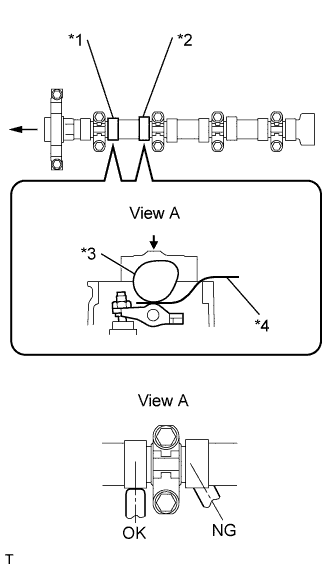
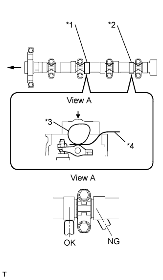
Text in Illustration *1 No. 1 Exhaust *2 No. 2 Intake *3 Camshaft *4 Feeler Gauge Check the valve clearance of the No. 1 cylinder exhaust valve and the No. 2 cylinder intake valve.
-
Using a feeler gauge, measure the clearance between the camshaft and No. 1 valve rocker arm.
Valve clearance (cold) 0.11 to 0.17 mm (0.004 to 0.007 in.) for intake 0.14 to 0.20 mm (0.006 to 0.008 in.) for exhaust Note
-
Insert the feeler gauge into the center of the roller surface, parallel to the No. 1 valve rocker arm.
-
Do not apply excessive force to the valve adjusting screw when using adjusting tools such as SST and a screwdriver.
Tech Tips
If the clearance is not as specified, record the out-of-specification measurement, and then adjust the valve clearance.
-
-
-
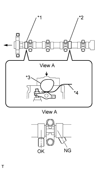
Text in Illustration *1 No. 1 Intake *2 No. 3 Exhaust *3 Camshaft *4 Feeler Gauge Check the valve clearance of the No. 1 cylinder intake valve and the No. 3 cylinder exhaust valve.
-
Turn the crankshaft by a further 180° clockwise.
-
Using a feeler gauge, measure the clearance between the camshaft and No. 1 valve rocker arm as shown in the illustration.
Valve clearance (cold) 0.11 to 0.17 mm (0.004 to 0.007 in.) for intake 0.14 to 0.20 mm (0.006 to 0.008 in.) for exhaust Note
-
Insert the feeler gauge into the center of the roller surface, parallel to the No. 1 valve rocker arm.
-
Do not apply excessive force to the valve adjusting screw with adjusting tools when measuring or adjusting.
Tech Tips
If the clearance is not as specified, record the out-of-specification measurement, and then adjust the valve clearance.
-
-
-
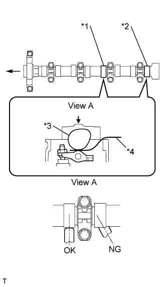
Text in Illustration *1 No. 3 Intake *2 No. 4 Exhaust *3 Camshaft *4 Feeler Gauge Check the valve clearances of the No. 3 cylinder intake valve and No. 4 cylinder exhaust valve.
-
Turn the crankshaft clockwise by a further 180°.
-
Using a feeler gauge, measure the clearance between the camshaft and No. 1 valve rocker arm as shown in the illustration.
Valve clearance (cold) 0.11 to 0.17 mm (0.004 to 0.007 in.) for intake 0.14 to 0.20 mm (0.006 to 0.008 in.) for exhaust Note
-
Insert the feeler gauge into the center of the roller surface, parallel to the No. 1 valve rocker arm.
-
Do not apply excessive force to the valve adjusting screw with adjusting tools when measuring or adjusting.
Tech Tips
If the clearance is not as specified, record the out-of-specification measurement, and then adjust the valve clearance.
-
-
-
Text in Illustration *1 No. 2 Exhaust *2 No. 4 Intake *3 Camshaft *4 Feeler Gauge Check the valve clearances of the No. 2 cylinder intake valve and No. 4 cylinder intake valve.
-
Turn the crankshaft clockwise by a further 180°.
-
Using a feeler gauge, measure the clearance between the camshaft and No. 1 valve rocker arm.
Valve clearance (cold) 0.11 to 0.17 mm (0.004 to 0.007 in.) for intake 0.14 to 0.20 mm (0.006 to 0.008 in.) for exhaust Note
-
Insert the feeler gauge into the center of the roller surface, parallel to the No. 1 valve rocker arm.
-
Do not apply excessive force to the valve adjusting screw with adjusting tools when measuring or adjusting.
Tech Tips
If the clearance is not as specified, record the out-of-specification measurement, and then adjust the valve clearance.
-
-
-
-
ADJUST VALVE CLEARANCE
-
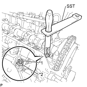
Text in Illustration *1 Adjusting Screw *2 Lock Nut Using SST and a screwdriver, loosen the valve adjusting nut while keeping the valve adjusting screw in position.
- SST
- 09248-56010
-
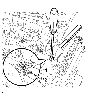
Text in Illustration *1 Adjusting Screw *2 Lock Nut *3 Feeler Gauge Adjust valve clearance (intake side).
-
Insert a feeler gauge (0.14 mm (0.006 in.)) between the camshaft and No. 1 valve rocker arm, and turn the valve adjusting screw to adjust it.
Valve clearance (cold) 0.14 mm (0.006 in.) -
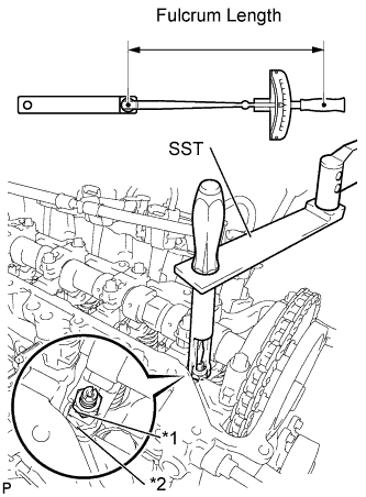
Text in Illustration *1 Adjusting Screw *2 Lock Nut Using SST and a screwdriver, tighten the valve adjusting nut while keeping the valve adjusting screw in position.
- Torque:
- With SST
- 13 N*m { 133 kgf*cm, 10 ft.*lbf }
- Without SST
- 20 N*m { 204 kgf*cm, 15 ft.*lbf }
Tech Tips
-
This torque wrench value can be obtained by using a torque wrench with a fulcrum length of 300 mm (11.81 in.) and SST with a fulcrum length of 150 mm (5.91 in.) Click here.
-
This torque value is effective when SST is parallel to a torque wrench.
-
-
Adjust the valve clearance (exhaust side).
Valve clearance (cold) 0.17 mm (0.007 in.) Tech Tips
Perform the same procedure as for the intake valve clearance adjustment.
-
-
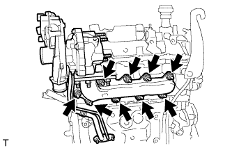
INSTALL CYLINDER HEAD COVER SUB-ASSEMBLY
-
Install the cylinder head gasket onto the cylinder head cover.
-
Apply seal packing to the 4 locations shown in the illustration, and then install the cylinder head cover.
Seal packing Toyota Genuine Seal Packing Black, Three Bond 1207B or equivalent Note
-
Remove any oil from the contact surface.
-
Install the cylinder head cover within 3 minutes, and tighten the bolts within 15 minutes of applying the seal packing.
-
-
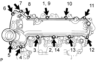
Temporarily tighten the cylinder head cover with the 12 bolts.
-
Fully tighten the 12 bolts, as shown in the illustration.
- Torque:
- 11 N*m { 112 kgf*cm, 8 ft.*lbf }
-
-
INSTALL HARNESS BRACKET (w/o Air Conditioning System)
-
Install the harness bracket with the bolt.
- Torque:
- 13 N*m { 130 kgf*cm, 9 ft.*lbf }
-
-
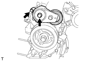
INSTALL V-RIBBED BELT TENSIONER ASSEMBLY
-
Install the V-ribbed belt tensioner with the 2 bolts.
- Torque:
- 24 N*m { 245 kgf*cm, 18 ft.*lbf }
-
-
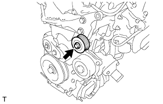
INSTALL IDLER PULLEY SUB-ASSEMBLY
-
Install the idler pulley with the bolt.
- Torque:
- 40 N*m { 408 kgf*cm, 30 ft.*lbf }
-
-
INSTALL VACUUM PUMP ASSEMBLY
-
Install 2 new O-rings to the vacuum pump.
-
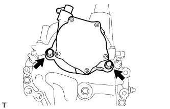
Install the vacuum pump with the 2 bolts.
- Torque:
- 21 N*m { 214 kgf*cm, 15 ft.*lbf }
-
-
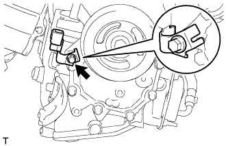
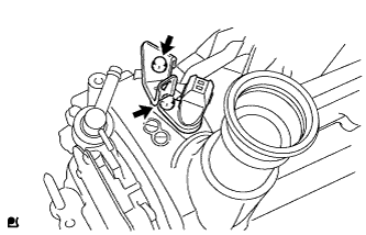
INSTALL CAMSHAFT POSITION SENSOR
-
Install the camshaft position sensor with the bolt.
- Torque:
- 7.0 N*m { 71 kgf*cm, 62 in.*lbf }
-
Install the harness bracket with the bolt.
- Torque:
- 11 N*m { 112 kgf*cm, 8 ft.*lbf }
-
-
INSTALL OIL LEVEL DIPSTICK GUIDE
-
Install a new O-ring to the oil level dipstick guide.
-
Install the oil level dipstick guide with the 2 bolts.
- Torque:
- 9.0 N*m { 92 kgf*cm, 80 in.*lbf }
-
-
INSTALL OIL LEVEL DIPSTICK
-
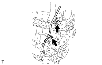
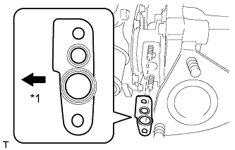
INSTALL WATER BY-PASS PIPE SUB-ASSEMBLY
-
Install a new O-ring to the water by-pass pipe.
-
Install the water by-pass pipe with the 2 bolts, as shown in the illustration.
- Torque:
- 9.0 N*m { 92 kgf*cm, 80 in.*lbf }
-
Connect the water by-pass hose.
-
Connect the oil cooler hose.
-
-
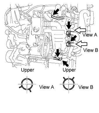
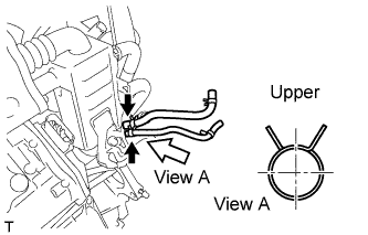
INSTALL NO. 4 WATER BY-PASS HOSE
-
Install the No. 4 water by-pass hose.
-
-
INSTALL NO. 2 OIL COOLER HOSE
Text in Illustration *1 Paint Mark
-
Install the No. 2 oil cooler hose.
Note
Align the oil cooler hose paint mark with the clamp center.
-
Text in Illustration *1 Paint Mark Install the hose clamp.
Note
Align the oil cooler hose paint mark with the clamp center.
-
-
INSTALL NO. 2 CYLINDER HEAD COVER
-
Install the No. 2 cylinder head cover.
-
Install the 2 harness brackets with the 2 bolts.
- Torque:
- 11 N*m { 112 kgf*cm, 8 ft.*lbf }
-
-
INSTALL NO. 1 INTAKE MANIFOLD INSULATOR
-
Install the No. 1 intake manifold insulator.
-
-
INSTALL COMMON RAIL ASSEMBLY
-
Install the common rail with 2 bolts.
- Torque:
- 21 N*m { 214 kgf*cm, 15 ft.*lbf }
-
-
INSTALL SUPPLY PUMP DRIVE COUPLING
-
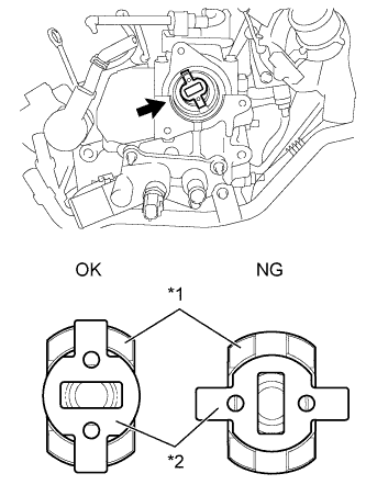
Text in Illustration *1 Camshaft *2 Supply Pump Drive Coupling Install the supply pump drive coupling into the camshaft.
Note
Install the supply pump drive coupling in the correct direction.
-
-
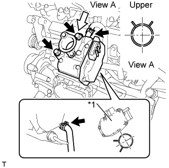
TEMPORARILY TIGHTEN SUPPLY PUMP ASSEMBLY
Note
When installing, clean the seal surfaces of the fuel inlet pipe, supply pump and common rail.
-
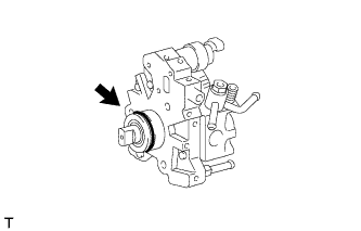
Apply a light coat of engine oil to a new O-ring.
-
Install the O-ring onto the supply pump.
-
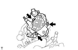
Temporarily tighten the supply pump with the 3 bolts.
-
-
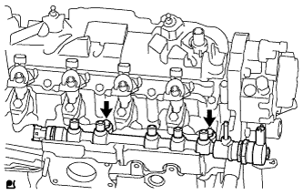
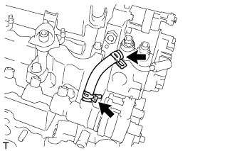
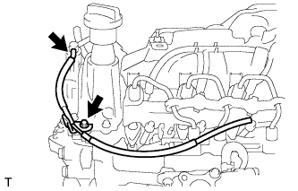
INSTALL FUEL INLET PIPE SUB-ASSEMBLY
Note
-
When replacing the supply pump. the fuel inlet pipe must also be replaced.
-
Replace the fuel inlet pipe with a new one when the fuel inlet pipe has been removed and reinstalled more than 5 times.
-
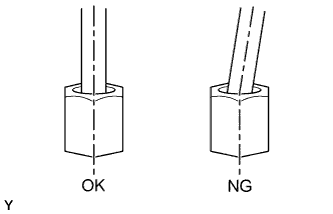
Temporarily tighten the fuel inlet pipe onto the supply pump and common rail.
Note
Install the pipe and union nut vertically. not at a tilt.
-
Fully tighten the supply pump with the 3 bolts.
- Torque:
- 21 N*m { 214 kgf*cm, 15 ft.*lbf }
-
Using a union nut wrench (17 mm), tighten the fuel inlet pipe union nut on the common rail side.
- Torque:
- 28 N*m { 286 kgf*cm, 20 ft.*lbf }
Note
Use the formula to calculate special torque values for situations where a union nut wrench is combined with a torque wrench Click here.
-
Using a wrench (17 mm), hold the supply pump nut, and using a union nut wrench (17 mm), tighten the fuel inlet pipe union nut on the supply pump side.
- Torque:
- 28 N*m { 286 kgf*cm, 20 ft.*lbf }
Note
Use the formula to calculate special torque values for situations where a union nut wrench is combined with a torque wrench Click here.
-
-
INSTALL NO. 2 FUEL HOSE
-
Install the No. 2 fuel hose.
-
-
INSTALL INJECTION NOZZLE SEAT
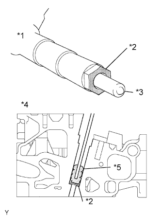
Text in Illustration *1 Injector *2 Sealing Surface *3 Nozzle *4 Cylinder Head *5 Cloth Note
-
When installing, clean the sealing surface of the injector, injection pipe and common rail.
-
When replacing the injectors, the injection pipes must also be replaced.
-
Replace the injection pipe with a new one when the injection pipe has been removed and reinstalled more than 5 times.
-
Replace the injector with one with the same part number and install it onto the cylinder.
-
Using a cloth and solvent, wipe away any carbon from the sealing surface of the injector and injector installation hole, as shown in the illustration.
Note
-
Do not damage the sealing surface.
-
Do not touch the injector nozzle.
-
-
Install 4 new nozzle seats onto the cylinder head.
-
-
INSTALL INJECTOR ASSEMBLY
-
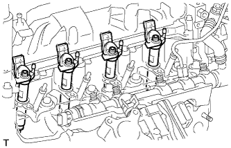
Install the 4 injectors onto the cylinder head.
Tech Tips
Fit the injectors into the seats.
-
-
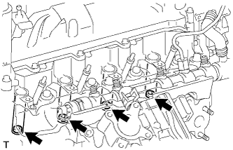
INSTALL NO. 1 NOZZLE HOLDER CLAMP
-
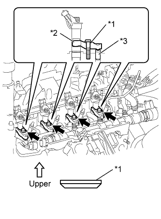
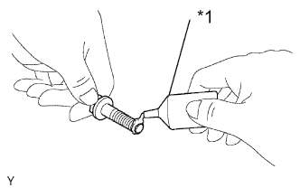
Text in Illustration *1 Washer *2 Nozzle holder clamp *3 Nozzle holder clamp seat Install the 4 nozzle holder clamps onto the injectors.
-
Set the washer on the nozzle holder clamp, as shown illustration.
Note
Install the washer in the correct direction.
-
Tighten the 4 nozzle holder clamp bolts.
- Torque:
- 19 N*m { 194 kgf*cm, 14 ft.*lbf }
-
-
INSTALL NOZZLE LEAKAGE PIPE ASSEMBLY
-
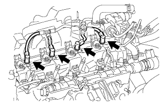
Install the nozzle leakage pipe into each injector.
-
Make sure the lock bush is at top position.
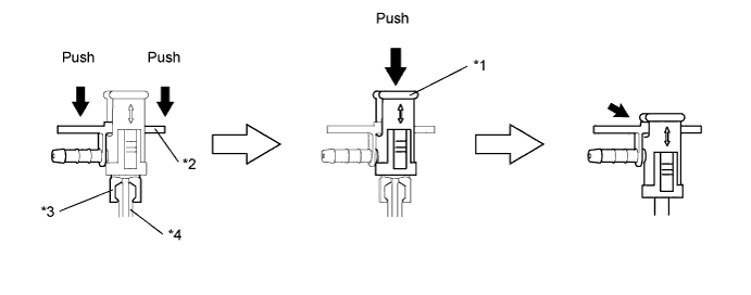
Text in Illustration *1 Lock Bush *2 Return Plug *3 Rest Arm *4 Injector -
Insert the rest arm into the injector and push both sides of the return plug until the rest arm engages with the injector, as shown in the illustration.
Tech Tips
Push the nozzle leakage pipe until it makes a click sound.
-
Push the lock bush until the it fits with the return plug, as shown in the illustration.
-
-
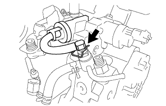
Connect the nozzle leakage pipe and install new retainer spring onto the supply pump.
-
-
INSTALL NOZZLE LEAKAGE PIPE SET CLAMP
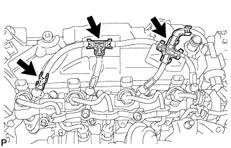
-
Install the 3 nozzle leakage pipe set clamps.
-
-
INSTALL NO. 2 INTAKE MANIFOLD INSULATOR
-
Install the No. 2 intake manifold insulator.
-
-
INSTALL GLOW PLUG ASSEMBLY
-
Clean the glow plug installation holes in the cylinder head.
-
Install the 4 glow plugs.
- Torque:
- 13 N*m { 127 kgf*cm, 9 ft.*lbf }
-
-
INSTALL NO. 1 GLOW PLUG CONNECTOR
-
Install the No. 1 glow plug connector with the 4 nuts.
- Torque:
- 2.2 N*m { 22 kgf*cm, 19 in.*lbf }
-
Install the 4 screw grommets.
-
-
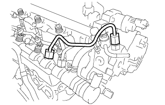
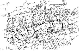
INSTALL NO. 1 INJECTION PIPE SUB-ASSEMBLY
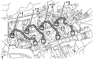
Text in Illustration *1 No. 1 Injection Pipe *2 No. 2 Injection Pipe *3 No. 3 Injection Pipe
-
Temporarily install 4 new injection pipes onto the injectors and common rail.
Note
Install the pipe and union nut vertically, not at a tilt.
-
Using a union nut wrench (17 mm), tighten the injection pipe union nut on the common rail, and then tighten the union nut on the injector.
- Torque:
- 28 N*m { 286 kgf*cm, 20 ft.*lbf }
Note
Use the formula to calculate special torque values for situations where a union nut wrench is combined with a torque wrench Click here.
-
-
INSTALL NO. 2 INJECTION PIPE SUB-ASSEMBLY
Tech Tips
Perform the same procedure as for injection pipe No. 1.
-
INSTALL NO. 3 INJECTION PIPE SUB-ASSEMBLY
Tech Tips
Perform the same procedure as for injection pipe No. 1.
-
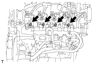
INSTALL NO. 1 INJECTION PIPE CLAMP
-
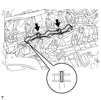
Install both sides of the No. 1 injection pipe clamp with the 2 nuts as shown in the illustration.
- Torque:
- 9.0 N*m { 92 kgf*cm, 80 in.*lbf }
-
-
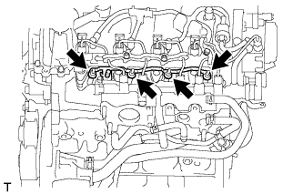
INSTALL NO. 2 INJECTION PIPE CLAMP
-
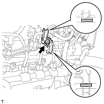
Install both sides of the No. 2 injection pipe clamp with the nut as shown in the illustration.
- Torque:
- 9.0 N*m { 92 kgf*cm, 80 in.*lbf }
-
-
INSTALL INTAKE AIR CONNECTOR WITH DIESEL THROTTLE BODY
-
Install the new gasket to the cylinder head.
-
Install the intake air connector with the diesel throttle body with the 2 bolts and 2 nuts.
- Torque:
- 23 N*m { 235 kgf*cm, 17 ft.*lbf }
-
-
INSTALL ELECTRIC EGR CONTROL VALVE ASSEMBLY
-
Install a new gasket.
-
Text in Illustration *1 Adhesive Apply adhesive to the 2 bolts.
Adhesive Toyota Genuine Adhesive 1324, Three Bond 1324 or equivalent. -
Text in Illustration *1 EGR Control Valve Install the electric EGR control valve with the 2 bolts.
- Torque:
- 23 N*m { 235 kgf*cm, 17 ft.*lbf }
-
Connect the No. 3 water by-pass hose.
-
Connect the No. 4 water by-pass hose.
-
-
INSTALL HARNESS BRACKET
-
Install the harness bracket with the bolt.
- Torque:
- 10 N*m { 102 kgf*cm, 7 ft.*lbf }
-
Connect the vacuum hose to the vacuum pump.
-
-
INSTALL NO. 1 EGR COOLER BRACKET
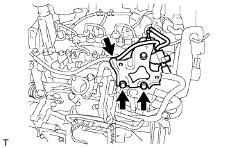
-
Install the No. 1 EGR cooler bracket with the 2 bolts.
- Torque:
- 23 N*m { 235 kgf*cm, 17 ft.*lbf }
-
Connect the vacuum hose.
-
-
INSTALL EGR WITH COOLER PIPE ASSEMBLY
-
Install 2 new gaskets.
-
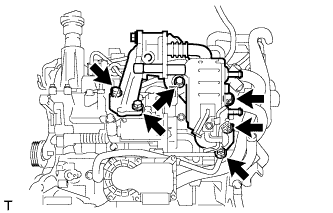
Install the EGR with cooler pipe assembly with the 4 bolts and 2 nuts.
- Torque:
- 23 N*m { 235 kgf*cm, 17 ft.*lbf }
-
Connect the No. 2 water by-pass hose.
-
Connect the No. 2 oil cooler hose.
-
Connect the 2 vacuum hoses and No. 1 oil hose.
-
Connect the No. 1 vacuum transmitting hose.
-
Connect the vacuum transmitting hose.
-
-
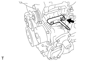
INSTALL GENERATOR BRACKET
-
Install the No. 1 generator bracket with the bolt.
- Torque:
- 40 N*m { 407 kgf*cm, 30 ft.*lbf }
-
-
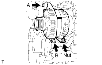
INSTALL GENERATOR ASSEMBLY
-
Install the generator with the 2 bolts and nut.
- Torque:
- Bolt A
- 21 N*m { 214 kgf*cm, 15 ft.*lbf }
- Bolt B, Nut
- 54 N*m { 551 kgf*cm, 40 ft.*lbf }
-
-
INSTALL TURBOCHARGER SUB-ASSEMBLY WITH EXHAUST MANIFOLD
Text in Illustration *1 Compressor Side
-
Install a new gasket to the turbocharger.
-
Temporarily tighten the turbo oil inlet pipe with the 2 nuts to the turbocharger.
-
Install 2 new gaskets to the cylinder head and cylinder block.
-
Install the turbocharger with the exhaust manifold with the 9 nuts.
- Torque:
- 43 N*m { 438 kgf*cm, 32 ft.*lbf }
-
Temporarily tighten the turbo oil inlet pipe with the 2 nuts to the cylinder block.
-
Fully tighten the 4 nuts.
Tech Tips
Fully tighten the nuts on the turbocharger side before tightening the nuts on the cylinder block.
- Torque:
- Turbocharger Side
- 11 N*m { 112 kgf*cm, 8 ft.*lbf }
- Cylinder Block Side
- 9.0 N*m { 92 kgf*cm, 80 in.*lbf }
-
-
INSTALL MANIFOLD STAY
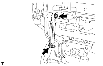
-
Install the manifold stay with the 2 bolts.
- Torque:
- 37 N*m { 377 kgf*cm, 27 ft.*lbf }
-
-
INSTALL NO. 2 TURBOCHARGER STAY
-
Temporarily tighten the No. 2 turbocharger stay with the bolt and nut.
-
Fully tighten the nut on the turbocharger side before tightening the bolt on the cylinder head side.
- Torque:
- 37 N*m { 377 kgf*cm, 27 ft.*lbf }
-
-
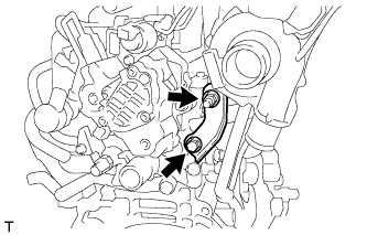
INSTALL TURBOCHARGER STAY
-
Temporarily tighten the turbocharger stay with the 2 bolts and nut.
-
Fully tighten the nut on the turbocharger side before tightening the bolts on the cylinder head side.
- Torque:
- 37 N*m { 377 kgf*cm, 27 ft.*lbf }
-
-
INSTALL NO. 1 TURBO INSULATOR
-
Install the No. 1 turbo insulator with the 2 bolts.
- Torque:
- 7.0 N*m { 71 kgf*cm, 62 in.*lbf }
-
-
INSTALL ENGINE ASSEMBLY
-
Install the engine assembly Click here.
-