VALVE CLEARANCE ADJUSTMENT

-
DISCONNECT CABLE FROM NEGATIVE BATTERY TERMINAL
-
REMOVE NO. 3 ENGINE UNDER COVER
-
Remove the 3 clips and the No. 3 engine under cover.
-
-
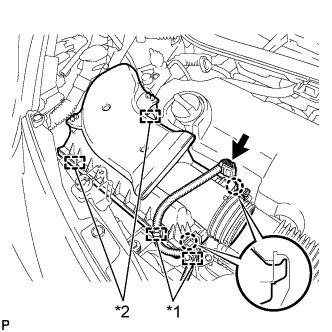
REMOVE AIR CLEANER CAP SUB-ASSEMBLY
-
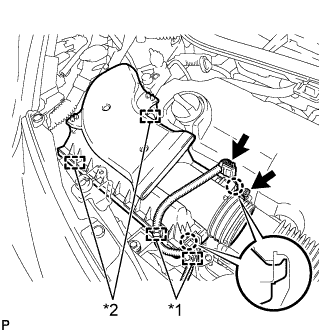
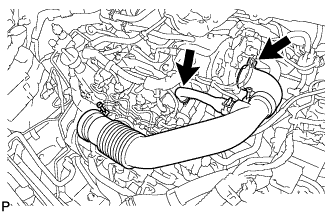
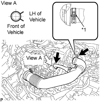
Text in Illustration *1 Wire harness clamp *2 Clamp Disconnect the connector and 2 wire harness clamps.
-
Loosen the hose clamp and separate the air cleaner hose.
-
Disengage the 2 clamps and 2 claws and remove the air cleaner cap.
-
-
REMOVE AIR CLEANER FILTER ELEMENT SUB-ASSEMBLY
-
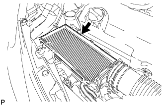
Remove the air cleaner filter element.
-
-
REMOVE AIR CLEANER CASE SUB-ASSEMBLY
-
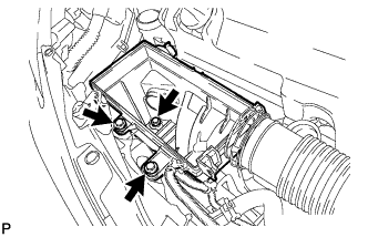
Remove the 3 bolts and the air cleaner case.
-
-
REMOVE AIR CLEANER HOSE ASSEMBLY
-
Remove the air cleaner hose.
-
-
REMOVE ENGINE COVER ASSEMBLY
-
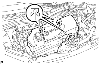
Disengage the 3 claws and remove the engine cover.
-
-
SEPARATE ENGINE WIRE
-
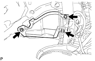
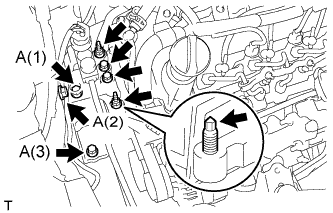
REMOVE ENGINE MOUNTING INSULATOR SUB-ASSEMBLY RH
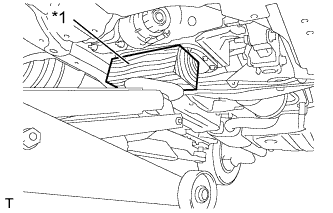
Text in Illustration *1 Wooden Block
-
Support the engine with a jack and a wooden block, as shown in the illustration.
-
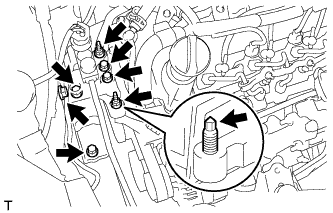
Remove the 5 bolts and 2 nuts.
-
Remove the stud bolt from the engine mounting bracket.
-
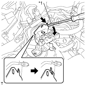
Text in Illustration *1 Protective Tape Using a screwdriver with its tip wrapped in protective tape, disengage the claw and remove the engine mounting insulator.
-
-
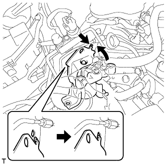
REMOVE VACUUM PUMP ASSEMBLY
-
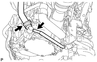
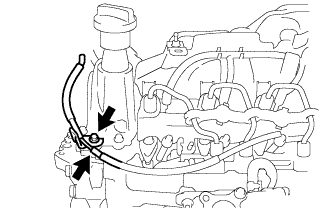
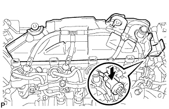
Slide the clip and disconnect the 2 vacuum hoses.
-
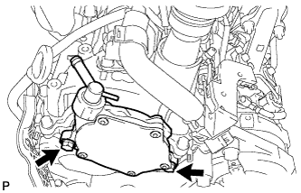
Remove the 2 bolts and vacuum pump assembly.
-
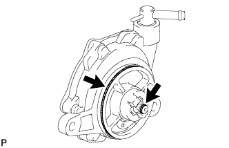
Remove the 2 O-rings from the vacuum pump assembly.
-
-
REMOVE NO. 2 CYLINDER HEAD COVER
-
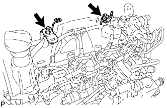
Remove the 2 bolts, 2 harness brackets and the No. 2 cylinder head cover.
-
Remove the 3 fuel pipe clamps.
-

Separate the fuel check valve from the No. 2 cylinder head cover.
-
Remove the No. 2 cylinder head cover.
-
-
REMOVE CYLINDER HEAD COVER SUB-ASSEMBLY
-
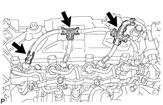
Disconnect the vacuum hose.
-
Remove the bolt and wire harness bracket.
-
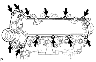
Remove the 12 bolts and the cylinder head cover.
-
-
CHECK VALVE CLEARANCE
-
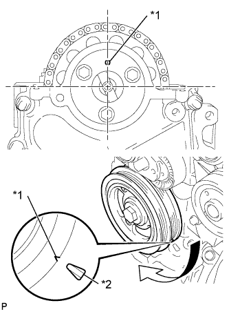
Text in Illustration *1 Timing Mark *2 TDC Mark Set the No. 1 cylinder to TDC/Compression.
-
Turn the crankshaft pulley until the grooves of the crankshaft damper and oil pump are aligned.
-
Check that the timing mark of the camshaft timing sprocket is in the position shown in the illustration.
Tech Tips
If not, turn the crankshaft damper 1 revolution (360°) to align the timing mark and sprocket as above.
-
-
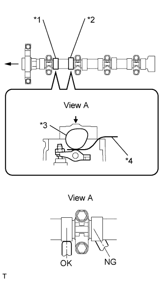
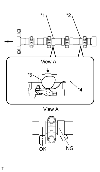
Text in Illustration *1 No. 1 Exhaust *2 No. 2 Intake *3 Camshaft *4 Feeler Gauge Check the valve clearance of the No. 1 cylinder exhaust valve and the No. 2 cylinder intake valve.
-
Using a feeler gauge, measure the clearance between the camshaft and No. 1 valve rocker arm.
Valve clearance (cold) 0.11 to 0.17 mm (0.004 to 0.007 in.) for intake 0.14 to 0.20 mm (0.006 to 0.008 in.) for exhaust Note
-
Insert the feeler gauge into the center of the roller surface, parallel to the No. 1 valve rocker arm.
-
Do not apply excessive force to the valve adjusting screw when using adjusting tools such as SST and a screwdriver.
Tech Tips
If the clearance is not as specified, record the out-of-specification measurement, and then adjust the valve clearance.
-
-
-
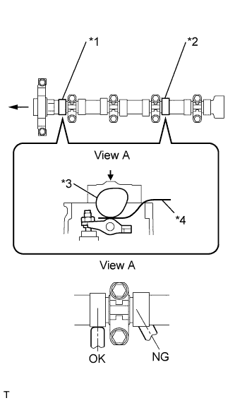
Text in Illustration *1 No. 1 Intake *2 No. 3 Exhaust *3 Camshaft *4 Feeler Gauge Check the valve clearance of the No. 1 cylinder intake valve and the No. 3 cylinder exhaust valve.
-
Turn the crankshaft by a further 180° clockwise.
-
Using a feeler gauge, measure the clearance between the camshaft and No. 1 valve rocker arm as shown in the illustration.
Valve clearance (cold) 0.11 to 0.17 mm (0.004 to 0.007 in.) for intake 0.14 to 0.20 mm (0.006 to 0.008 in.) for exhaust Note
-
Insert the feeler gauge into the center of the roller surface, parallel to the No. 1 valve rocker arm.
-
Do not apply excessive force to the valve adjusting screw with adjusting tools when measuring or adjusting.
Tech Tips
If the clearance is not as specified, record the out-of-specification measurement, and then adjust the valve clearance.
-
-
-
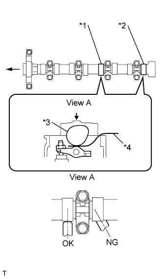
Text in Illustration *1 No. 3 Intake *2 No. 4 Exhaust *3 Camshaft *4 Feeler Gauge Check the valve clearances of the No. 3 cylinder intake valve and No. 4 cylinder exhaust valve.
-
Turn the crankshaft clockwise by a further 180°.
-
Using a feeler gauge, measure the clearance between the camshaft and No. 1 valve rocker arm as shown in the illustration.
Valve clearance (cold) 0.11 to 0.17 mm (0.004 to 0.007 in.) for intake 0.14 to 0.20 mm (0.006 to 0.008 in.) for exhaust Note
-
Insert the feeler gauge into the center of the roller surface, parallel to the No. 1 valve rocker arm.
-
Do not apply excessive force to the valve adjusting screw with adjusting tools when measuring or adjusting.
Tech Tips
If the clearance is not as specified, record the out-of-specification measurement, and then adjust the valve clearance.
-
-
-
Text in Illustration *1 No. 2 Exhaust *2 No. 4 Intake *3 Camshaft *4 Feeler Gauge Check the valve clearances of the No. 2 cylinder intake valve and No. 4 cylinder intake valve.
-
Turn the crankshaft clockwise by a further 180°.
-
Using a feeler gauge, measure the clearance between the camshaft and No. 1 valve rocker arm.
Valve clearance (cold) 0.11 to 0.17 mm (0.004 to 0.007 in.) for intake 0.14 to 0.20 mm (0.006 to 0.008 in.) for exhaust Note
-
Insert the feeler gauge into the center of the roller surface, parallel to the No. 1 valve rocker arm.
-
Do not apply excessive force to the valve adjusting screw with adjusting tools when measuring or adjusting.
Tech Tips
If the clearance is not as specified, record the out-of-specification measurement, and then adjust the valve clearance.
-
-
-
-
ADJUST VALVE CLEARANCE
-
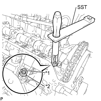
Text in Illustration *1 Adjusting Screw *2 Lock Nut Using SST and a screwdriver, loosen the valve adjusting nut while keeping the valve adjusting screw in position.
- SST
- 09248-56010
-
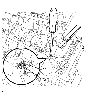
Text in Illustration *1 Adjusting Screw *2 Lock Nut *3 Feeler Gauge Adjust valve clearance (intake side).
-
Insert a feeler gauge (0.14 mm (0.006 in.)) between the camshaft and No. 1 valve rocker arm, and turn the valve adjusting screw to adjust it.
Valve clearance (cold) 0.14 mm (0.006 in.) -
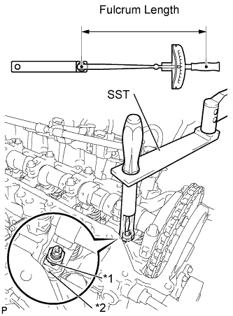
Text in Illustration *1 Adjusting Screw *2 Lock Nut Using SST and a screwdriver, tighten the valve adjusting nut while keeping the valve adjusting screw in position.
- Torque:
- With SST
- 13 N*m { 133 kgf*cm, 10 ft.*lbf }
- Without SST
- 20 N*m { 204 kgf*cm, 15 ft.*lbf }
Tech Tips
-
This torque wrench value can be obtained by using a torque wrench with a fulcrum length of 300 mm (11.81 in.) and SST with a fulcrum length of 150 mm (5.91 in.) Click here.
-
This torque value is effective when SST is parallel to a torque wrench.
-
-
Adjust the valve clearance (exhaust side).
Valve clearance (cold) 0.17 mm (0.007 in.) Tech Tips
Perform the same procedure as for the intake valve clearance adjustment.
-
-
INSTALL CYLINDER HEAD COVER SUB-ASSEMBLY
-
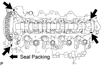
Apply seal packing to the 4 locations as shown in the illustration, and then install the cylinder head cover.
Seal packing Toyota Genuine Seal Packing Black, Three Bond 1207B or equivalent Note
-
Remove any oil from the contact surface.
-
Install the cylinder head cover within 3 minutes, and tighten the bolts within 15 minutes of applying the seal packing.
-
-
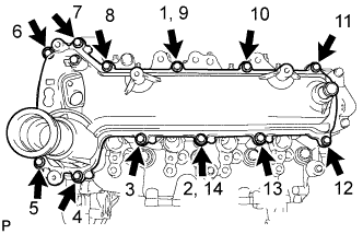
Temporarily tighten the cylinder head cover with the 12 bolts.
-
Fully tighten the 12 bolts, as shown in the illustration.
- Torque:
- 11 N*m { 112 kgf*cm, 8 ft.*lbf }
-
Install the wire harness bracket.
- Torque:
- 10 N*m { 102 kgf*cm, 7 ft.*lbf }
-
Connect the vacuum hose.
-
-
INSTALL NO. 2 CYLINDER HEAD COVER
-
Install the No. 2 cylinder head cover.
-
Install the fuel check valve onto the No. 2 cylinder head cover.
-
Install the 3 fuel pipe clamps.
-
Install the No. 2 cylinder head cover with the 2 bolts and 2 harness brackets.
- Torque:
- 11 N*m { 112 kgf*cm, 8 ft.*lbf }
-
-
INSTALL VACUUM PUMP ASSEMBLY
-
Coat 2 new O-rings with engine oil, and place them onto the vacuum pump assembly.
-
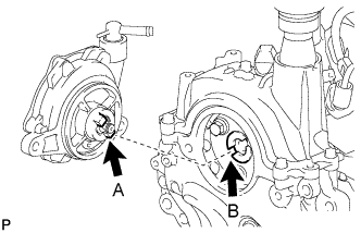
Install the vacuum pump assembly so that the coupling teeth A on the side of the vacuum pump can engage with the tip groove of camshaft B.
-
Install 2 new bolts onto the vacuum pump assembly.
- Torque:
- 21 N*m { 214 kgf*cm, 15 ft.*lbf }
-
Connect the 2 vacuum hoses with the clip to the vacuum pump assembly.
-
-
INSTALL ENGINE MOUNTING INSULATOR SUB-ASSEMBLY RH
-
Engage the claw and install the engine mounting insulator.
-
Install the stud bolt to the engine mounting bracket.
- Torque:
- 10 N*m { 102 kgf*cm, 7 ft.*lbf }
-
Temporarily tighten the engine mounting insulator with the 5 bolts and 2 nuts.
-
Fully tighten the 3 bolts to the body, as shown in the illustration.
- Torque:
- Bolt A
- 52 N*m { 530 kgf*cm, 38 ft.*lbf }
-
Fully tighten the 2 bolts and 2 nuts to the engine.
- Torque:
- 52 N*m { 530 kgf*cm, 38 ft.*lbf }
-
-
CONNECT ENGINE WIRE
-
INSTALL ENGINE COVER ASSEMBLY
-
Engage the 3 claws and install the engine cover.
-
-
INSTALL AIR CLEANER CASE SUB-ASSEMBLY
-
Install the air cleaner case with the 3 bolts.
- Torque:
- 7.5 N*m { 76 kgf*cm, 66 in.*lbf }
-
-
INSTALL AIR CLEANER FILTER ELEMENT SUB-ASSEMBLY
-
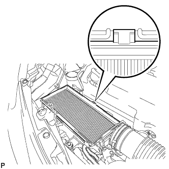
Install the air cleaner filter element.
Note
Engage the air cleaner filter element protrusion with the air cleaner case groove.
-
-
INSTALL AIR CLEANER CAP SUB-ASSEMBLY
-
Engage the 2 claws and 2 clamps and install the air cleaner cap.
-
Connect the connector and 2 wire harness clamps.
Text in Illustration *1 Wire harness clamp *2 Clamp -
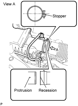
Connect the air cleaner hose to the air cleaner cap.
Tech Tips
-
The clamp should contact the air cleaner hose stopper.
-
Make sure that the air cleaner hose recession is securely engaged with the air cleaner cap protrusion.
-
-
-
INSTALL AIR CLEANER HOSE ASSEMBLY
Text in Illustration *1 Paint Mark
-
Install the air cleaner hose.
Note
Position the clip so that the claws are centered over the paint mark on the hose.
-
-
INSTALL NO. 3 ENGINE UNDER COVER
-
Install the No. 3 engine under cover with the 3 clips.
-
-
CONNECT CABLE TO NEGATIVE BATTERY TERMINAL
- Torque:
- 5.4 N*m { 55 kgf*cm, 48 ft.*lbf }