ENGINE UNIT INSTALLATION

-
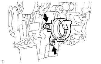
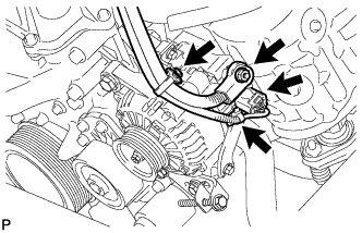
INSTALL DRIVE SHAFT BEARING BRACKET
-
Install the drive shaft bearing bracket with the 2 bolts.
- Torque:
- 64 N*m { 650 kgf*cm, 47 ft.*lbf }
-
-
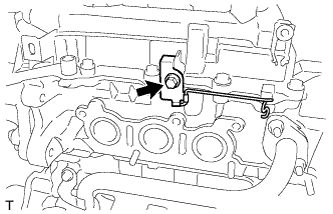
INSTALL WIRING HARNESS CLAMP BRACKET
-
Install the wiring harness clamp bracket with the bolt.
- Torque:
- 12 N*m { 122 kgf*cm, 9 ft.*lbf }
-
-
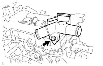
INSTALL WATER FILLER ASSEMBLY
-
Install the water filler assembly with the bolt.
- Torque:
- 13 N*m { 127 kgf*cm, 10 ft.*lbf }
-
-
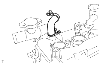
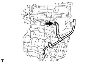
INSTALL NO. 2 VENTILATION HOSE
-
Install the No. 2 ventilation hose with the clip.
-
-
INSTALL OIL LEVEL DIPSTICK GUIDE SUB-ASSEMBLY
-
Install the new O-ring to the oil level dipstick guide sub-assembly.
-
Install the oil level dipstick guide sub-assembly with the bolt.
- Torque:
- 10 N*m { 102 kgf*cm, 7 ft.*lbf }
-
-
INSTALL OIL LEVEL DIPSTICK SUB-ASSEMBLY
-
INSTALL IDLER PULLEY
-
Install the idler pulley with the 3 bolts.
- Torque:
- 25 N*m { 255 kgf*cm, 18 ft.*lbf }
-
-
INSTALL ENGINE WIRE
-
Install the engine wire with the 4 bolts.
- Torque:
- 8.0 N*m { 82 kgf*cm, 71 in.*lbf }
-
Connect all the connectors and the harness clamps.
-
-
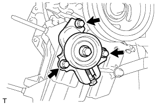
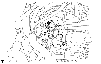
INSTALL VACUUM SWITCHING VALVE ASSEMBLY
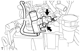
-
Install the vacuum switching valve assembly with the bolt.
- Torque:
- 14 N*m { 143 kgf*cm, 10 ft.*lbf }
-
Connect the vacuum switching valve assembly connector.
-
-
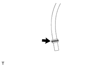
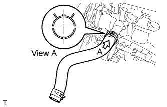
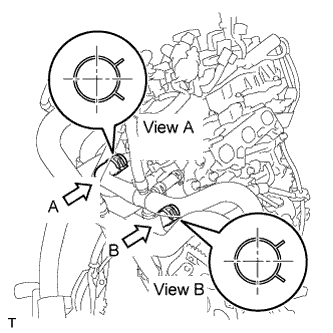
INSTALL NO. 2 RADIATOR HOSE
-
Install the No. 2 radiator hose with the clip.
Tech Tips
Install the clip as shown in the illustration.
-
-
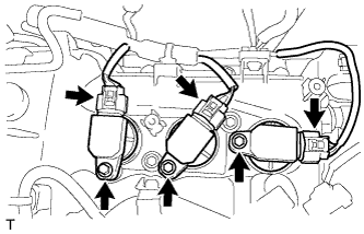
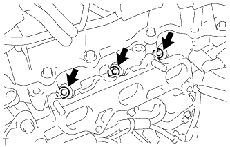
INSTALL NO. 1 IGNITION COIL
-
Install the 3 No. 1 ignition coils with the 3 bolts.
- Torque:
- 9.0 N*m { 91 kgf*cm, 80 in.*lbf }
-
Connect the 3 No. 1 ignition coil connectors.
-
-
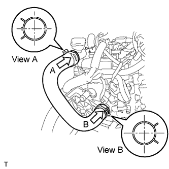
INSTALL NO. 1 RADIATOR HOSE
-
Install the No. 1 radiator hose with the 2 clips.
Tech Tips
Install the clip as shown in the illustration.
-
-
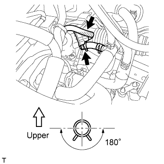
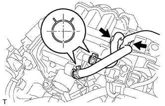
INSTALL WATER BY-PASS HOSE ASSEMBLY
-
Install the water by-pass hose assembly with the 2 clips.
Tech Tips
Install the clips as shown in the illustration.
-
-
INSTALL INJECTOR VIBRATION INSULATOR
-
Install 3 new injector vibration insulators to the cylinder head.
-
-
INSTALL FUEL INJECTOR ASSEMBLY
-
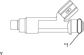
Text in Illustration *1 O-ring Apply a light coat of gasoline or spindle oil to the contact surfaces of a new O-ring, and install it onto the injector.
-
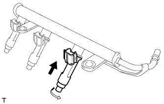
While turning the fuel injector assembly left and right, install it onto the fuel delivery pipe.
Note
-
Do not twist the O-ring.
-
Check that the fuel injector assemblies rotate smoothly after installing it onto the fuel delivery pipe. If the fuel injector assembly does not rotate smoothly, replace the O-ring with a new one and install it again.
-
-
-
INSTALL FUEL PIPE INSULATOR
-
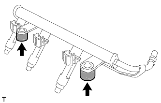
Install the 2 fuel pipe insulators onto the fuel delivery pipe.
-
-
INSTALL FUEL DELIVERY PIPE
-
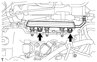
Install the fuel delivery pipe with the 2 bolts.
- Torque:
- 27 N*m { 275 kgf*cm, 20 ft.*lbf }
Note
-
Do not drop the fuel injector assembly.
-
After installing, check that the fuel injector assembly is securely connected by turning it by hand.
-
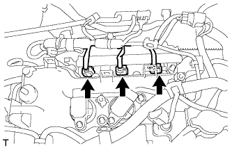
Connect the 3 fuel injector assembly connectors.
-
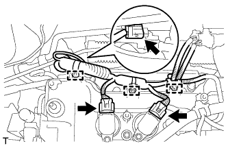
Engage the 3 harness clamps and connect the 3 connectors.
-
-
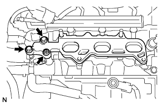
INSTALL EGR VALVE ASSEMBLY
-
Install a new gasket to the cylinder head.
-
Insert the EGR valve into the stud bolt, rotate the EGR valve to avoid contact with the delivery pipe, and temporarily install the EGR valve.
-
Connect the water by-pass hose.
-
Connect the EGR valve connector.
-
-
INSTALL NO. 1 INTAKE MANIFOLD INSULATOR
-
Temporarily install the intake manifold insulator with a new gasket, the 2 bolts and the nut.
-
-
INSTALL INTAKE MANIFOLD
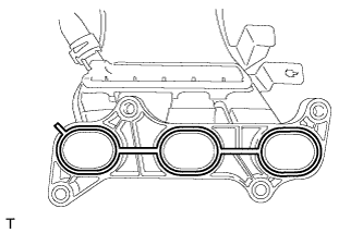
-
Install the new gasket onto the intake manifold.
-
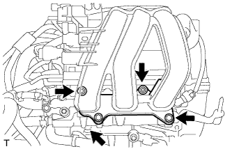
Install the intake manifold with the 2 bolts and 2 nuts in the order shown in the illustration.
- Torque:
- 30 N*m { 306 kgf*cm, 22 ft.*lbf }
-
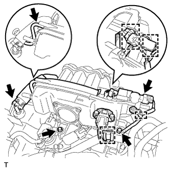
Connect the vacuum hose, ventilation hose and install the 2 bolts.
- Torque:
- 9.0 N*m { 92 kgf*cm, 80 in.*lbf }
-
Connect the 2 connectors and 4 harness clamps.
-
-
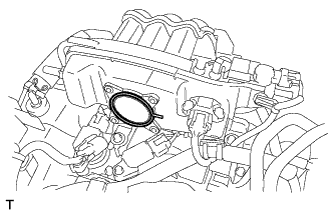
INSTALL THROTTLE WITH MOTOR BODY ASSEMBLY
-
Install the new gasket onto the intake manifold.
-
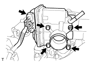
Install the throttle with motor body assembly with the 3 bolts and nut.
- Torque:
- 10 N*m { 102 kgf*cm, 7 ft.*lbf }
-
Connect the throttle with motor body assembly connector.
-
Connect the 2 water by-pass hoses with the 2 clips.
Tech Tips
Install the clips as shown in the illustration.
-
Install the 2 water by-pass hoses to the hose clamp.
-
-
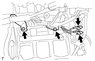
INSTALL GENERATOR ASSEMBLY
-
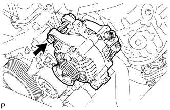
Temporarily install the generator assembly with the bolt.
-
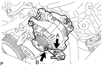
Temporarily install the fan belt adjusting bar with bolt A and bolt B.
-
Tighten bolt B with the generator assembly near the cylinder block.
- Torque:
- 21 N*m { 214 kgf*cm, 16 ft.*lbf }
-
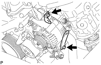
Install the 2 brackets with the 2 bolts.
- Torque:
- 8.0 N*m { 82 kgf*cm, 71 in.*lbf }
-
Connect the connector and wire harness clamps.
-
Install the terminal B with the nut.
- Torque:
- 9.8 N*m { 100 kgf*cm, 87 in.*lbf }
-
Install the terminal cap.
-