ENGINE UNIT INSPECTION

-
CLEAN CYLINDER HEAD
-
Using a scraper, clean the cylinder block surface and manifold of the cylinder head.
CAUTION:
-
Wear protective goggles while servicing.
-
Do not damage the cylinder head.
-
Do not drop cylinder head gasket material into the water jacket.
-
-
-
CLEAN CYLINDER BLOCK
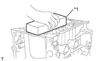
Text in Illustration *1 Oil Stone
-
Using an oil stone or similar device, clean the chain cover surface, cylinder head surface, oil pan surface, and ventilation baffle plate surface of the cylinder block.
CAUTION:
Wear protective goggles while servicing.
Note
-
Do not damage the cylinder block while servicing.
-
Do not drop any cylinder head gasket material into the water jacket.
-
-
-
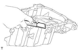
CLEAN OIL PAN
-
Clean the installation surface of the oil pan.
-
-
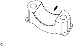
CLEAN CAMSHAFT BEARING CAP
-
Clean the installation surfaces of the No. 1 camshaft bearing cap and No. 2 camshaft bearing caps.
-
-
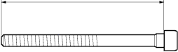
INSPECT CYLINDER HEAD SET BOLT
-
Using a vernier caliper, measure the cylinder head bolt length.
Maximum length 123.5 mm (4.862 in.) If the length is greater than the maximum, replace the cylinder head bolt.
-
-
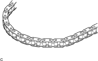
INSPECT CHAIN SUB-ASSEMBLY
-
Visually check the timing chain for wear or cracks.
If the timing chain is not normal, replace the timing chain and check the sprocket.
-
-
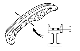
INSPECT TIMING CHAIN TENSION ARM
-
Inspect the wear of the timing chain tension arm.
Maximum thickness 0.5 mm (0.02 in.) If the thickness is greater than the maximum, replace the timing chain tension arm.
-
-
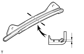
INSPECT TIMING CHAIN GUIDE
-
Check the timing chain guide.
Maximum thickness 0.5 mm (0.02 in.) If the thickness is greater than the maximum, replace the timing chain guide.
-
-
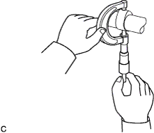
INSPECT NO. 1 CHAIN TENSIONER ASSEMBLY
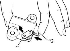
Text in Illustration *1 Stopper Plate *2 Plunger
-
While holding the stopper plate of No. 1 chain tensioner assembly with your fingers, check that the plunger operates smoothly.
-
Release the stopper plate and check that the plunger cannot be pushed with the stopper plate activated.
If No. 1 chain tensioner assembly is not as specified, replace No. 1 chain tensioner assembly.
-
-
INSPECT CAMSHAFT
-
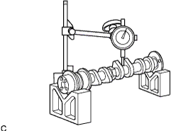
Inspect the camshaft for runout.
-
Using V-blocks and a dial indicator, measure the runout of the 3rd journal.
Maximum circle runout 0.03 mm (0.0012 in.) Tech Tips
The runout is the half of the value on the indicator when the camshaft is turned 1 revolution.
If the circle runout is greater than the maximum, replace the camshaft.
-
-
Inspect the cam lobes.
-
Using a micrometer, measure the cam lobe height.
Standard Cam Lobe Height Item Specification No. 1 Camshaft 41.54 to 41.64 mm (1.6354 to 1.6394 in.) No. 2 Camshaft 40.97 to 41.07 mm (1.6310 to 1.6169 in.) Minimum Cam Lobe Height Item Specification No. 1 Camshaft 41.44 mm (1.6315 in.) No. 2 Camshaft 40.87 mm (1.6091 in.) If the cam lobe height is less than the minimum, replace the camshaft.
-
-
-
INSPECT CAMSHAFT TIMING SPROCKET ASSEMBLY
-
Check the camshaft timing sprocket assembly for wear and damage.
If the camshaft timing sprocket is not in good condition, replace the camshaft timing sprocket.
-
Install the camshaft timing sprocket assembly.
-
Check the camshaft timing camshaft timing sprocket assembly lock.
-
Make sure that the camshaft timing sprocket assembly is locked.
-
-
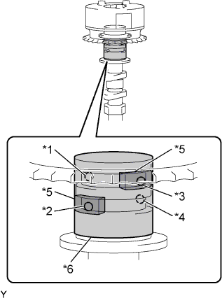
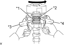
Text in Illustration *1 Advance Side Path (Open) *2 Retard Side Path (Close) *3 Advance Side Path (Close) *4 Retard Side Path (Open) *5 Rubber *6 Vinyl Tape Release the lock pin.
-
Cover the 4 oil paths of the cam journal with vinyl tape as shown in the illustration.
Tech Tips
4 oil paths are provided in the groove. Plug 2 paths with rubber pieces.
-
Prick a hole in the tape placed on the advance side path. Prick a hole in the tape placed on the retard side path, on the opposite side to that of the advance side path, as shown in the illustration.
-
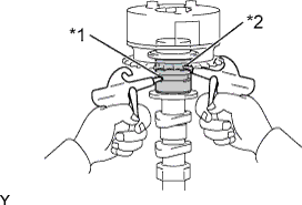
Text in Illustration *1 Retard Side Path *2 Advance Side Path Apply approximately 200 kPa (2.0 kgf/cm2, 28 psi) of air pressure to the 2 paths (the advance side path and the retard side path).
CAUTION:
Cover the paths with a piece of cloth when applying pressure to keep oil from splashing.
-
Text in Illustration *1 Retard Side Path *2 Advance Side Path *3 Decompress *4 Hold Pressure Make sure that the camshaft timing sprocket turns in the retard direction when reducing the air pressure applied to the advance side path.
Tech Tips
The lock pin is released and the camshaft timing sprocket turns in the retard direction.
-
When the camshaft timing sprocket moves to the most retarded position, release the air pressure from the advance side path, and then release the air pressure from the retard side path.
Note
Be sure to release the air pressure from the advance side path first. If the air pressure of the retard side path is released first, the camshaft timing sprocket may abruptly shift in the advance direction and break the lock pin or other parts.
-
-
Check for smooth rotation.
-
Turn the camshaft timing exhaust gear within its movable range (25 to 50°) 2 or 3 times, but do not turn it to the most advanced position. Make sure that the gear turns smoothly.
Note
When the air pressure is released from the advance side path and then from the retard side path, the gear automatically returns to the most advanced position due to the advance assist spring operation and locks. Gradually release the air pressure from the retard side path before performing the smooth rotation check.
-
-
Check the lock at the most advanced position.
-
Make sure that the camshaft timing sprocket is locked at the most advanced position.
-
-
-
INSPECT CAMSHAFT TIMING GEAR OR SPROCKET
-
Check the camshaft timing gear or sprocket for wear and damage.
If the camshaft timing gear or sprocket is not in good condition, replace the camshaft timing gear or sprocket.
-
-
INSPECT CRANKSHAFT TIMING GEAR OR SPROCKET
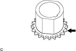
-
Check the crankshaft timing gear or sprocket for wear and damage.
If the crankshaft timing gear or sprocket is not in good condition, replace the crankshaft timing gear or sprocket.
-