FRONT CRANKSHAFT OIL SEAL INSTALLATION

-
INSTALL TIMING CHAIN COVER OIL SEAL
-
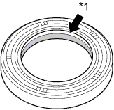
Apply MP grease to the lip of a new oil seal.
Text in Illustration *1 MP Grease Note
Keep the lip free of foreign matter.
-
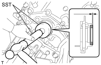
Using SST and a hammer, tap in the oil seal as shown in the illustration.
- SST
- 09950-60010 ( 09951-00500, 09952-06010 )
- 09950-70010 ( 09951-00720 )
Standard depth -1.0 to 0.5 mm (-0.0394 to 0.0197 in.) Note
-
Wipe off extra grease from the crankshaft.
-
Do not tap the oil seal at an angle.
-
-
INSTALL CRANKSHAFT PULLEY
-
Align the pulley set key with the key groove of the pulley.
-
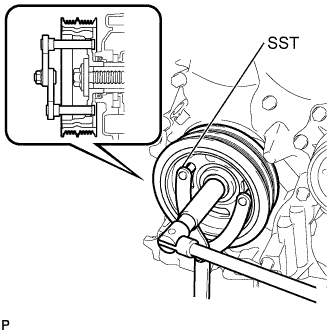
Using SST, hold the pulley in place and tighten the bolt.
- SST
- 09960-10010 ( 09962-01000, 09963-01000 )
- Torque:
- 180 N*m { 1835 kgf*cm, 133 ft.*lbf }
-
-
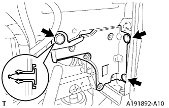
INSTALL ENGINE MOUNTING INSULATOR SUB-ASSEMBLY RH
-
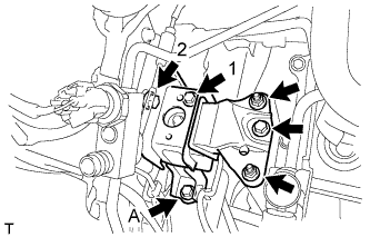
Temporarily tighten the bolt A.
-
Tighten the 2 bolts on the vehicle side in the sequence shown in the illustration.
- Torque:
- 52 N*m { 530 kgf*cm, 38 ft.*lbf }
-
Fully tighten the bolt A.
- Torque:
- 52 N*m { 530 kgf*cm, 38 ft.*lbf }
-
Tighten the bolt and 2 nuts on the engine side and install the engine mounting insulator RH.
-
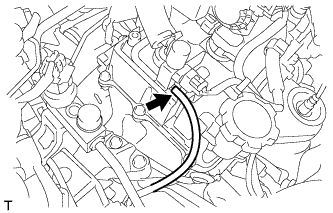
Connect the vacuum hose to the vacuum switching valve assembly.
-
-
CONNECT DISCHARGE HOSE SUB-ASSEMBLY
-
Apply sufficient compressor oil to a new O-ring and the fitting surface of the tube joint.
Compressor oil ND-OIL8 or equivalent -
Install the O-ring onto the discharge hose.
-
Connect the discharge hose sub-assembly with the bolt.
- Torque:
- 5.0 N*m { 55 kgf*cm, 44 in.*lbf }
-
-
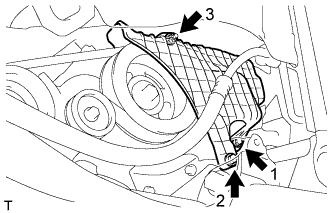
INSTALL FAN AND GENERATOR V BELT
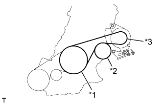
Text in Illustration *1 Crankshaft Pulley *2 Water Pump Assembly *3 Generator Assembly
-
Temporarily install the V-ribbed belt onto each pulley.
Note
-
Before installing the V-ribbed belt, check each pulley for any kind of liquid and chips.
-
Check that the ribs of the V-ribbed belt are correctly fitted into the grooves of the pulleys.
-
-
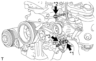
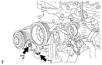
Text in Illustration *1 Bolt B *2 Bolt A *3 Bolt C Turn the bolt B to adjust the tension of the V-ribbed belt.
-
Tighten fixing bolts A and C.
- Torque:
- Bolt A
- 54 N*m { 551 kgf*cm, 40 ft.*lbf }
- Bolt C
- 21 N*m { 214 kgf*cm, 15 ft.*lbf }
-
-
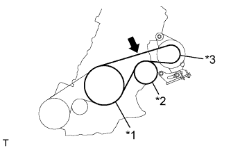
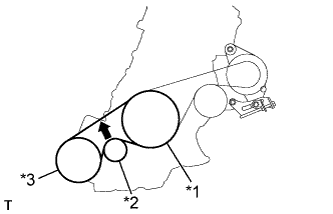
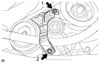
INSTALL NO. 1 V (COOLER COMPRESSOR TO CRANKSHAFT PULLEY) BELT
Text in Illustration *1 Crankshaft Pulley *2 Idler Pulley *3 Cooler Compressor Assembly
-
Temporarily install the V-ribbed belt onto each pulley.
Note
-
Before installing the V-ribbed belt, check each pulley for any kind of liquid and chips.
-
Check that the ribs of the V-ribbed belt are correctly fitted into the grooves of the pulleys.
-
-
Text in Illustration *1 Bolt B *2 Bolt A Turn the bolt B to adjust the tension of the V-ribbed belt.
-
Tighten bolt A.
-
-
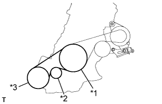
INSPECT FAN AND GENERATOR V BELT
-
Text in Illustration *1 Crankshaft Pulley *2 Water Pump Pulley *3 Generator Pulley 
Specified Point Check the fan and generator V-ribbed belt deflection (when inspecting a vehicle without the No. 1 engine cover installed).
Deflection Pressing Force
N (kg, Ib)
New Belt
mm (in.)
Used Belt
mm (in.)
10
(10, 22)
8.0 to 10.5
(0.315 to 0.413)
11.0 to 14.0
(0.433 to 0.551)
Note
-
Check the belt deflection between the pulleys at the indicated measurement point (directly between the pulleys).
-
When installing a new belt, set its deflection value as specified.
-
When checking a belt used for over 5 minutes, confirm that the deflection value is within the specified range for a used belt.
-
When reinstalling a belt used for over 5 minutes, check whether its deflection value is within the specified range for a used belt.
-
-
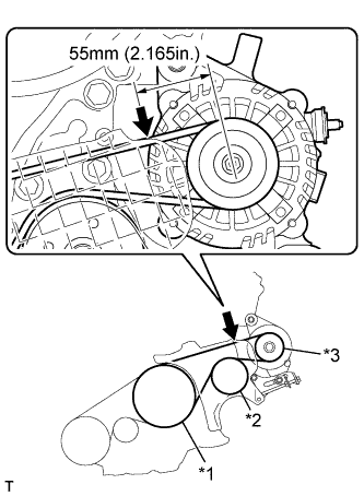
Text in Illustration *1 Crankshaft Pulley *2 Water Pump Pulley *3 Generator Pulley Specified Point Check the fan and generator V-ribbed belt deflection (when inspecting a vehicle while the No. 1 engine cover is installed).
Deflection Pressing Force
N (kg, Ib)
New Belt
mm (in.)
Used Belt
mm (in.)
10
(10, 22)
4.5 to 6.0
(0.177 to 0.236)
6.5 to 7.5
(0.256 to 0.295)
Note
-
Check the belt deflection between the pulleys at the indicated measurement point (on the left side of the generator pulley, 55 mm (2.165 in.) from the center of the pulley).
-
When installing a new belt, set its deflection value as specified.
-
When checking a belt used for over 5 minutes, confirm that the deflection value is within the specified range for a used belt.
-
When reinstalling a belt used for over 5 minutes, check whether its deflection value is within the specified range for a used belt.
-
-
-
INSPECT NO. 1 V (COOLER COMPRESSOR TO CRANKSHAFT PULLEY) BELT
-
Text in Illustration *1 Crankshaft Pulley *2 Idler Pulley *3 Cooler Compressor Assembly Specified Point Check the No. 1 (cooler compressor to crankshaft pulley) belt.
Deflection Pressing Force
N (kg, Ib)
New Belt
mm (in.)
Used Belt
mm (in.)
10
(10, 22)
8.0 to 10.0
(0.315 to 0.394)
11.0 to 14.0
(0.433 to 0.551)
Note
-
Check the No. 1 (cooler compressor to crankshaft pulley) belt deflection at the specified point.
-
When installing a new belt, set its deflection value as specified.
-
When checking a belt used for over 5 minutes, confirm that the deflection value is within the specified range for a used belt.
-
When reinstalling a belt used for over 5 minutes, check whether its deflection value is within the specified range for a used belt.
-
-
-
ADD ENGINE OIL
-
Add new engine oil and install the oil filler cap.
Engine Oil Oil Grade Oil Viscosity (SAE)
-
API grade SL or SM multigrade engine oil
-
20W-50
-
15W-40
-
API grade SL "Energy-Conserving" "Energy-Conserving SM or ILSAC multigrade engine oil"
-
10W-30
-
5W-30
-
5W-20
-
0W-20
Capacity Item Standard Condition Drain and refill with oil filter change 3.1 liters (3.3 US qts, 2.7 Imp. qts) Drain and refill without oil filter change 2.9 liters (3.1 US qts, 2.6 Imp. qts) Dry fill 3.4 liters (3.6 US qts, 3.0 Imp. qts) -
-
-
INSPECT FOR ENGINE OIL LEAK
-
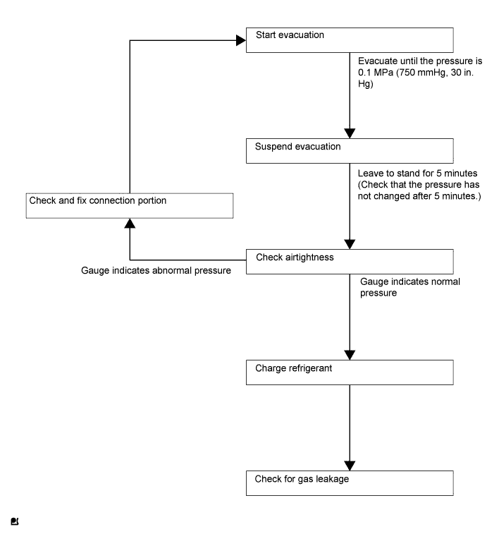
CHARGE REFRIGERANT
Tech Tips
Charge refrigerant in accordance with the equipment manual.
-
Perform vacuum purging using a vacuum pump.
-
Charge refrigerant HFC-134a (R134a).
- SST
- 09985-20010 ( 09985-02010, 09985-02050, 09985-02060, 09985-02070, 09985-02080, 09985-02090, 09985-02110, 09985-02130, 09985-02140, 09985-02150 )
Standard 330 to 390 g (11.6 to 13.8 oz.) Note
-
Do not start the engine before charging it with refrigerant as the cooler compressor does not work properly without sufficient refrigerant. This could cause the compressor to overheat.
-
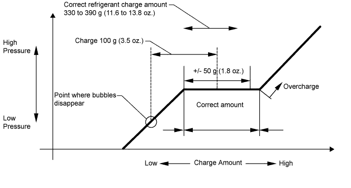
Approximately 100 g (3.5 oz.) of refrigerant may need to be charged after bubbles disappear.
The volume of refrigerant should be measured, not checked with the sight glass.
Tech Tips
-
The relationship between the refrigerant charge amount and the pressure is as follows.
-
High Charge Range:
If the refrigerant is overcharged, the pressure rises on the high-pressure side. High-pressure cut off frequently occurs. This causes insufficient cooling performance and also insufficient compressor lubrication.
-
Low Charge Range:
A shortage of refrigerant causes insufficient cooling performance and low circulation of refrigerant oil, which shortens the compressor life. Operation with insufficient coolant raises the refrigerant temperature and causes heat deterioration of the rubber seals and hoses. Cracking and subsequent refrigerant leakage may occur.
-
Install the caps onto the service valves on the refrigerant line.
-
-
WARM UP ENGINE
Note
Warm up the engine at less than 2000 rpm for 1 minute or more after charging it with refrigerant.
-
INSPECT REFRIGERANT LEAK
-
After recharging the refrigerant gas, check for refrigerant gas leakage using a halogen leak detector.
-
Perform the operation as follows:
-
Stop the engine.
-
Secure good ventilation (the halogen leak detector may react to volatile gases other than refrigerant, such as evaporated gasoline or exhaust gas).
-
Repeat the test 2 or 3 times.
-
Make sure that some refrigerant remains in the refrigeration system.
When the compressor is off: approximately 392 to 588 kPa (4 to 6 kgf/cm2, 57 to 85 psi)
Tech Tips
It is impossible for the above pressure to be maintained if there is leakage.
-
-
Using the halogen leak detector, check the refrigerant line, especially at the connection points, for leakage.
-
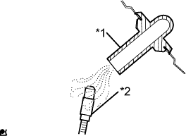
Text in illustration *1 Drain hose *2 Halogen leak detector Bring the halogen leak detector close to the drain hose before performing the test.
Tech Tips
-
After the blower motor has stopped, leave the cooling unit for at least 15 minutes.
-
Place the halogen leak detector sensor under the drain hose.
-
When bringing the halogen leak detector close to the drain hose, make sure that the halogen leak detector does not react to other volatile gases.
If such a reaction is unavoidable, the vehicle must be lifted up.
-
-
If no gas leakage is detected from the drain hose, remove the blower motor from the cooling unit. Insert the halogen leak detector sensor into the unit and perform the test.
-
Disconnect the pressure switch connector and leave it for approximately 20 minutes. Bring the halogen leak detector close to the pressure switch and perform the test.
-
-
INSTALL NO. 1 ENGINE COVER
-
Temporarily install the No. 1 engine cover with the 2 bolts and nut.
-
Fully tighten the 2 bolts and nut in the order shown in the illustration.
- Torque:
- 10 N*m { 102 kgf*cm, 7 ft.*lbf }
-
-
INSTALL NO. 1 COOLER COVER
-
Temporarily install the No. 1 cooler cover with the 2 nuts.
-
Fully tighten the 2 nuts in the order shown in the illustration.
- Torque:
- 9.8 N*m { 100 kgf*cm, 87 in.*lbf }
-
-
INSTALL ENGINE UNDER COVER RH
-
INSTALL NO. 3 ENGINE UNDER COVER
-
Install the No. 3 engine under cover with the 3 clips.
-