FRONT CRANKSHAFT OIL SEAL REMOVAL

-
REFRIGERANT FROM REFRIGERATION SYSTEM
-
Start up the engine.
-
Switch the A/C on.
-
Turn the blower switch to on.
-
Operate the cooler compressor with an engine speed of approximately 1000 rpm for 5 to 6 minutes to circulate the refrigerant and collect the remaining compressor oil from each component, in the cooler compressor.
-
Stop the engine.
-
Remove the caps from the service valves on the refrigerant line.
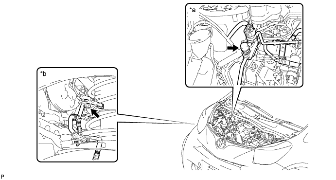
Text in illustration *a Engine room side *b Wheel house side Access to Hi Pressure Side Engine Type RHD LHD 1KR-FE Engine room Engine room 1NR-FE Engine room Engine room 1ND-TV Engine room Engine room Access to Low Pressure Side Engine Type RHD LHD 1KR-FE Wheel house Wheel house 1NR-FE Wheel house Wheel house 1ND-TV Wheel house Wheel house -
Connect the refrigerant recovery unit.
-
Recover the refrigerant from the air conditioning system using a refrigerant recovery unit.
Tech Tips
Use the refrigerant recovery unit in accordance with the manufacturer's instruction manual.
-
-
REMOVE NO. 3 ENGINE UNDER COVER
-
Remove the 3 clips and No. 3 engine under cover.
-
-
REMOVE ENGINE UNDER COVER RH
-
REMOVE NO. 1 COOLER COVER (w/ No. 1 Cooler Cover)
-
Remove the 2 nuts and the No. 1 cooler cover.
-
-
REMOVE NO. 1 ENGINE COVER (w/ No. 1 Engine Cover)
-
Remove the 2 bolts, nut and the No. 1 engine cover.
-
-
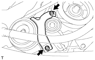
REMOVE NO. 1 V (COOLER COMPRESSOR TO CRANKSHAFT PULLEY) BELT
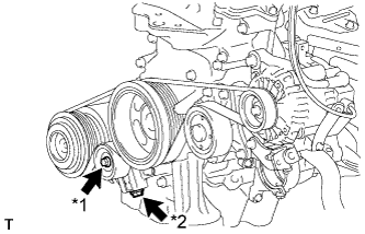
Text in Illustration *1 Bolt A *2 Adjusting Bolt B
-
Loosen the bolt A.
-
Turn adjusting bolt B to release the tension and remove the V belt from the pulleys.
-
-
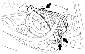
REMOVE FAN AND GENERATOR V BELT
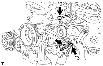
Text in Illustration *1 Bolt A *2 Bolt B *3 Bolt C
-
Loosen the bolt A and B.
-
Turn adjusting bolt C to release the tension and remove the V belt from the pulleys.
-
-
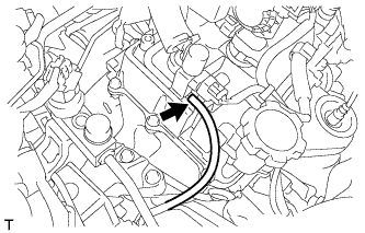
DISCONNECT DISCHARGE HOSE SUB-ASSEMBLY
-
Remove the bolt and disconnect the discharge hose sub-assembly.
-
Remove the O-ring from the discharge hose sub-assembly.
Tech Tips
Seal the openings of the disconnected parts using vinyl tape to prevent the entry of moisture and foreign matter.
-
-
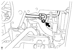
REMOVE ENGINE MOUNTING INSULATOR SUB-ASSEMBLY RH
-
Disconnect the vacuum hose from the vacuum switching valve assembly.
-
Place a wooden block between a floor jack and the engine, and then support the engine using the floor jack.
-
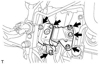
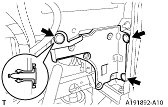
Remove the 4 bolts, 2 nuts and engine mounting insulator sub-assembly RH.
-
-
REMOVE CRANKSHAFT PULLEY
-
Operate the jack and slowly lower the engine.
Note
Do not lower the engine more than necessary.
-
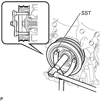
Using SST, hold the pulley in place and loosen the pulley bolt.
- SST
- 09960-10010 ( 09962-01000, 09963-01000 )
-
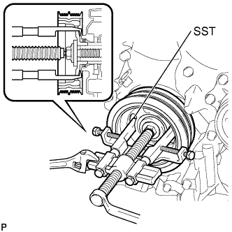
Using SST, remove the crankshaft pulley and pulley bolt.
- SST
- 09950-40011 ( 09951-04010, 09953-04030, 09958-04011, 09955-04011, 09954-04010, 09952-04010 )
-
-
REMOVE TIMING CHAIN COVER OIL SEAL
-
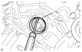
Text in Illustration *1 Protective Tape Using a knife, cut off the lip of the oil seal.
-
Using a screwdriver with its tip wrapped in protective tape, pry out the oil seal.
Note
After removing, check the crankshaft for damage. If damaged, smooth the surface with 400-grit sandpaper.
-