CAMSHAFT INSTALLATION

-
INSTALL CAMSHAFT TIMING SPROCKET ASSEMBLY
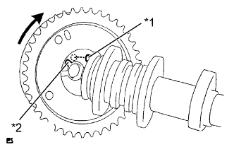
Text in Illustration *1 Straight Pin *2 Key Groove
-
Put the camshaft timing gear assembly and camshaft together with the straight pin and key groove misaligned, as shown in the illustration.
Note
Do not forcefully push in the camshaft timing gear assembly. This may cause the camshaft knock pin tip to damage the installation surface of the camshaft timing gear assembly.
-
-
INSTALL CAMSHAFT
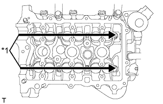
Text in Illustration *1 Apply Engine Oil
-
Apply engine oil to the cam of each camshaft, the journals of the cylinder head and the top of each valve lifter.
-
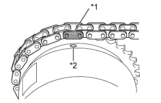
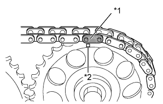
Text in Illustration *1 Paint Mark *2 Timing Mark Align the matchmarks on the timing chain plates with the timing mark of the camshaft timing sprocket assembly and the paint mark of the timing chain respectively and install the timing chain.
-
-
INSTALL NO. 2 CAMSHAFT
-
Apply engine oil to each cam of the No. 2 camshaft.
-
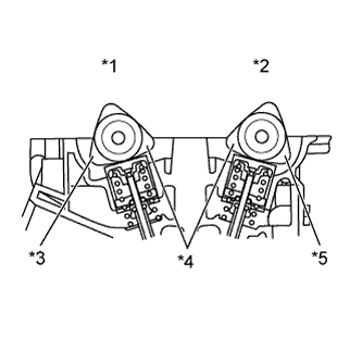
Text in Illustration *1 No. 1 Camshaft *2 No. 2 Camshaft *3 No. 3 Cylinder *4 No. 1 Cylinder *5 No. 2 Cylinder Install the camshafts as shown in the illustration.
Tech Tips
Make sure that the timing marks of the camshaft timing sprocket and camshaft timing sprocket face upward.
-
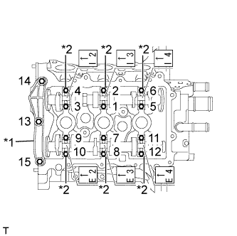
Text in Illustration *1 No. 1 Camshaft Bearing Cap *2 No. 2 Camshaft Bearing Cap Place the No. 1 camshaft bearing cap and No. 2 camshaft bearing caps and tighten the bolts to the specified torque in the order shown in the illustration.
- Torque:
- No. 1 camshaft bearing cap
- 15 N*m { 153 kgf*cm, 11 ft.*lbf }
- No. 2 camshaft bearing cap
- 13 N*m { 127 kgf*cm, 9 ft.*lbf }
Note
Install No. 1 camshaft bearing cap and No. 2 camshaft bearing caps with the front marks facing engine front.
-
-
INSTALL CAMSHAFT TIMING GEAR OR SPROCKET
-
Align the matchmarks on the timing chain plates with the timing mark of the camshaft timing gear or sprocket and the paint mark of the timing chain respectively and install the timing chain.
Text in Illustration *1 Paint Mark *2 Timing Mark -
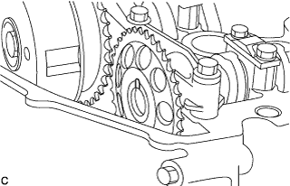
Install the No. 2 camshaft with the knock pin aligned with the gear groove.
Tech Tips
Position the timing mark of the gear at the top.
-
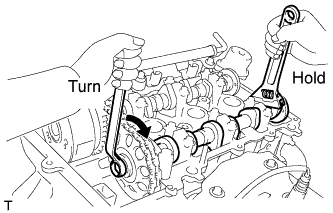
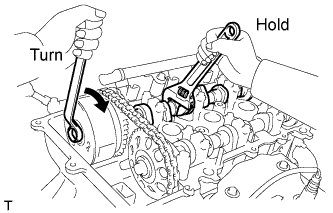
Tighten the bolts onto the timing gear while holding the hexagonal portion of the No. 2 camshaft.
- Torque:
- 47 N*m { 479 kgf*cm, 35 ft.*lbf }
-
-
INSTALL CAMSHAFT TIMING SPROCKET ASSEMBLY
-
Tighten the bolts onto the sprocket while holding the hexagonal portion of the camshaft.
- Torque:
- 47 N*m { 479 kgf*cm, 35 ft.*lbf }
-
-
INSTALL TIMING GEAR COVER TIGHT PLUG
-
Remove the hexagon wrench from the timing chain tensioner sub-assembly.
Tech Tips
Before removing, slightly turn the hexagonal portion of the camshaft assembly counterclockwise to leave some slack on the chain of the timing chain tensioner sub-assembly side.
-
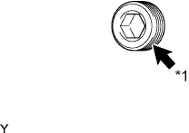
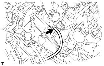
Text in Illustration *1 Adhesive Clean the plug and the bolt holes of the timing chain cover and apply adhesive to the threads of the plug.
Adhesive Toyota Genuine Adhesive 1324, Three Bond 1324 or equivalent -
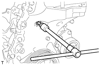
Using an 8 mm socket hexagon wrench, install the timing gear tight plug.
- Torque:
- 10 N*m { 102 kgf*cm, 7 ft.*lbf }
-
-
INSPECT VALVE CLEARANCE
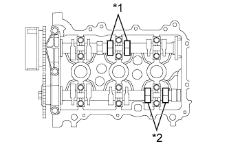
Text in Illustration *1 Intake Side *2 Exhaust Side
-
Check only the valves indicated.
-
Using a feeler gauge, measure the clearance between the valve lifter and camshaft.
Valve clearance (Cold) Intake side 0.145 to 0.235 mm (0.00571 to 0.00925 in.) Exhaust side 0.275 to 0.365 mm (0.01083 to 0.01437 in.) Tech Tips
Insert the feeler gauge from the spark plug side (center).
-
Record any out-of-specification valve clearance measurements. They will be used later to determine the required replacement valve lifters.
-
-
Turn the crankshaft 1 revolution (360°).
-
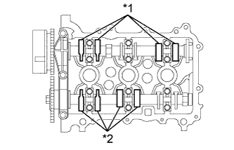
Text in Illustration *1 Intake Side *2 Exhaust Side Check only the valves indicated.
-
Using a feeler gauge, measure the clearance between the valve lifter and camshaft.
Valve clearance (Cold) Intake side 0.145 to 0.235 mm (0.00571 to 0.00925 in.) Exhaust side 0.275 to 0.365 mm (0.01083 to 0.01437 in.) Tech Tips
Insert the feeler gauge from the spark plug side (center).
-
Record any out-of-specification valve clearance measurements. They will be used later to determine the required replacement valve lifters.
-
-
-
ADJUST VALVE CLEARANCE
-
Remove the No. 1 and No. 2 camshafts Click here.
-
Remove the valve lifters Click here.
-
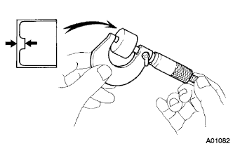
Using a micrometer, measure the thickness of the removed valve lifters.
-
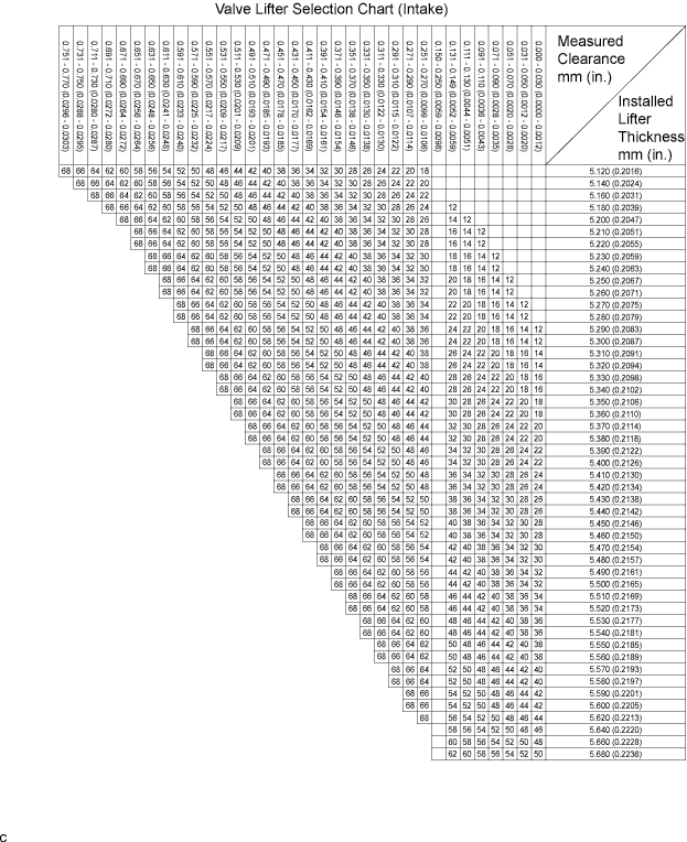
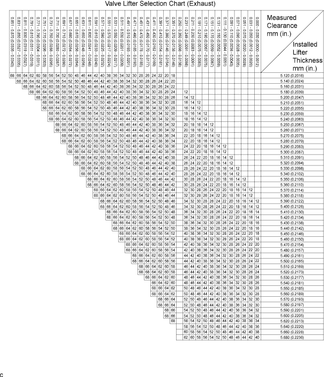
Calculate the thickness of a new lifter so that the valve clearance comes within the specified value.
A Thickness of new lifter B Thickness of used lifter C Measured valve clearance Valve clearance Intake A = B + (C - 0.18 mm (0.0071 in.)) Exhaust A = B + (C - 0.31 mm (0.0122 in.)) Tech Tips
-
Select a new lifter with a thickness as close to the calculated values as possible.
-
Lifters are available in 29 sizes in increments of 0.020 mm (0.0008 in.), from 5.12 mm (0.2016 in.) to 5.68 mm (0.2236 in.).
-
Refer to the New Lifter Thickness Table on the next 2 pages.
-
-
Install the valve lifters Click here.
-
Install the No. 1 and No. 2 camshafts Click here.
Tech Tips
New Lifter Thickness mm (in.) Lifter No. Thickness Lifter No. Thickness Lifter No. Thickness 12 5.12 (0.2016) 32 5.32 (0.2094) 52 5.52 (0.2173) 14 5.14 (0.2024) 34 5.34 (0.2102) 54 5.54 (0.2181) 16 5.16 (0.2031) 36 5.36 (0.2110) 56 5.56 (0.2189) 18 5.18 (0.2039) 38 5.38 (0.2118) 58 5.58 (0.2197) 20 5.20 (0.2047) 40 5.40 (0.2126) 60 5.60 (0.2205) 22 5.22 (0.2055) 42 5.42 (0.2134) 62 5.62 (0.2213) 24 5.24 (0.2063) 44 5.44 (0.2142) 64 5.64 (0.2220) 26 5.26 (0.2071) 46 5.46 (0.2150) 66 5.66 (0.2228) 28 5.28 (0.2079) 48 5.48 (0.2157) 68 5.68 (0.2236) 30 5.30 (0.2087) 50 5.50 (0.2165) - -
-
-
INSTALL CYLINDER HEAD COVER SUB-ASSEMBLY
-
Clean the cylinder head cover, cylinder head assembly and timing chain cover assembly.
-
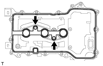
Fit the cylinder head cover gasket into the gasket groove on the cover and onto the center bosses.
-
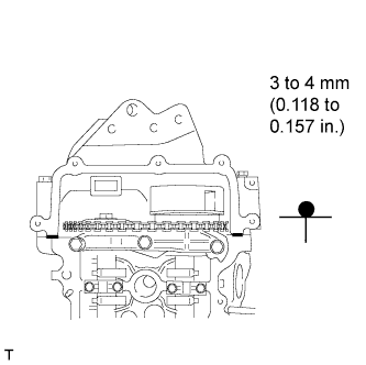
Apply a continuous bead of seal packing (diameter: 3 to 4 mm (0.118 to 0.157 in.)) to the contact surface between the cylinder head assembly and timing chain cover assembly, as shown in the illustration.
Seal packing Toyota Genuine Seal Packing Black, Three Bond 1207B or equivalent -
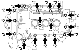
Text in Illustration *1 Bolt A *2 Bolt B Tighten the bolts A, and then the bolts B.
Note
After tightening all of the bolts, check that the bolts A meet the specified torque.
- Torque:
- 7.7 N*m { 79 kgf*cm, 68 in.*lbf }
-
Install the wire harness to the cylinder head cover sub-assembly.
-
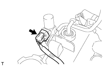
Connect the vacuum switching valve connector.
-
Connect the vacuum hose to the vacuum switching valve.
-
-
INSTALL OIL FILLER CAP SUB-ASSEMBLY
-
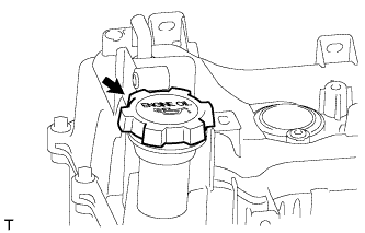
Install the oil filler cap sub-assembly.
-
-
INSTALL HARNESS BRACKET
-
Install the harness bracket with the bolt.
- Torque:
- 12 N*m { 122 kgf*cm, 9 ft.*lbf }
-
-
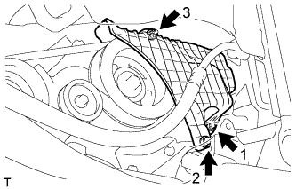
INSTALL WATER FILLER ASSEMBLY
-
Install the water filler assembly with the bolt.
- Torque:
- 13 N*m { 127 kgf*cm, 9 ft.*lbf }
-
Connect the No. 1 radiator hose and No. 3 radiator hose with the 2 clips.
-
-
CONNECT RADIATOR RESERVOIR TANK HOSE
-
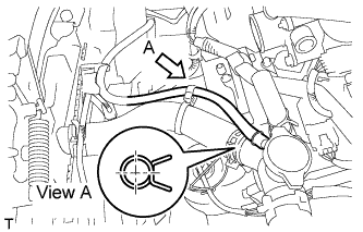
Connect the radiator reservoir tank hose with the clip.
Tech Tips
Install the clip as shown in the illustration.
-
-
INSTALL NO. 1 IGNITION COIL
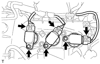
-
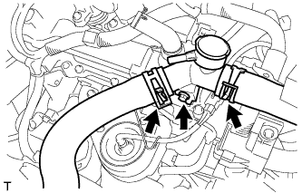
Install the 3 No. 1 ignition coils with the 3 bolts.
- Torque:
- 9.0 N*m { 91 kgf*cm, 80 in.*lbf }
-
Connect the 3 No. 1 ignition coil connectors.
-
-
INSTALL INTAKE MANIFOLD
-
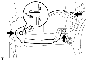
INSTALL NO. 1 ENGINE COVER
-
Temporarily install the No. 1 engine cover with the 2 bolts and nut.
-
Fully tighten the 2 bolts and nut in the order shown in the illustration.
- Torque:
- 10 N*m { 102 kgf*cm, 7 ft.*lbf }
-
-
INSTALL NO. 3 ENGINE UNDER COVER
-
Install the No. 3 engine under cover with the 3 clips.
-
-
CHECK FOR ENGINE OIL LEAKAGE