DRIVE BELT INSTALLATION

-
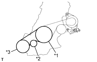
INSTALL FAN AND GENERATOR V BELT
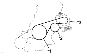
Text in Illustration *1 Crankshaft Pulley *2 Water Pump Assembly *3 Generator Assembly
-
Temporarily install the V-ribbed belt onto each pulley.
Note
-
Before installing the V-ribbed belt, check each pulley for any kind of liquid and chips.
-
Check that the ribs of the V-ribbed belt are correctly fitted into the grooves of the pulleys.
-
-
-
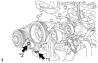
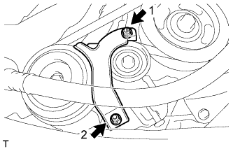
ADJUST FAN AND GENERATOR V BELT
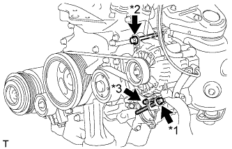
Text in Illustration *1 Bolt B *2 Bolt A *3 Bolt C
-
Turn the bolt B to adjust the tension of the V-ribbed belt.
-
Tighten fixing bolts A and C.
- Torque:
- Bolt A
- 54 N*m { 551 kgf*cm, 40 ft.*lbf }
- Bolt C
- 21 N*m { 214 kgf*cm, 15 ft.*lbf }
-
-
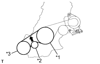
INSPECT FAN AND GENERATOR V BELT
-
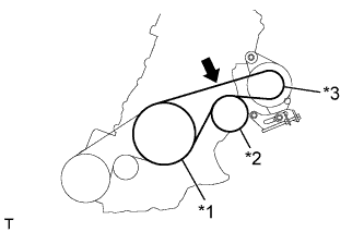
Text in Illustration *1 Crankshaft Pulley *2 Water Pump Pulley *3 Generator Pulley 
Specified Point Check the fan and generator V-ribbed belt deflection (when inspecting a vehicle w/o No. 1 engine cover, or without the No. 1 engine cover installed).
Deflection Pressing Force
N (kg, Ib)
New Belt
mm (in.)
Used Belt
mm (in.)
10
(10, 22)
8.0 to 10.5
(0.315 to 0.413)
11.0 to 14.0
(0.433 to 0.551)
Note
-
Check the belt deflection between the pulleys at the indicated measurement point (directly between the pulleys).
-
When installing a new belt, set its deflection value as specified.
-
When checking a belt used for over 5 minutes, confirm that the deflection value is within the specified range for a used belt.
-
When reinstalling a belt used for over 5 minutes, check whether its deflection value is within the specified range for a used belt.
-
-
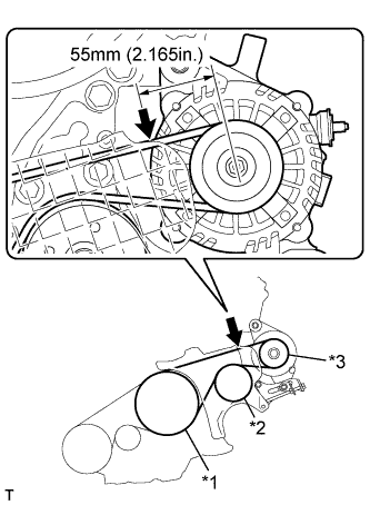
Text in Illustration *1 Crankshaft Pulley *2 Water Pump Pulley *3 Generator Pulley Specified Point Check the fan and generator V-ribbed belt deflection (when inspecting a vehicle while the No. 1 engine cover is installed).
Deflection Pressing Force
N (kg, Ib)
New Belt
mm (in.)
Used Belt
mm (in.)
10
(10, 22)
4.5 to 6.0
(0.177 to 0.236)
6.5 to 7.5
(0.256 to 0.295)
Note
-
Check the belt deflection between the pulleys at the indicated measurement point (on the left side of the generator pulley, 55 mm (2.165 in.) from the center of the pulley).
-
When installing a new belt, set its deflection value as specified.
-
When checking a belt used for over 5 minutes, confirm that the deflection value is within the specified range for a used belt.
-
When reinstalling a belt used for over 5 minutes, check whether its deflection value is within the specified range for a used belt.
-
-
-
INSTALL NO. 1 V (COOLER COMPRESSOR TO CRANKSHAFT PULLEY) BELT
Text in Illustration *1 Crankshaft Pulley *2 Idler Pulley *3 Cooler Compressor Assembly
-
Temporarily install the V-ribbed belt onto each pulley.
Note
-
Before installing the V-ribbed belt, check each pulley for any kind of liquid and chips.
-
Check that the ribs of the V-ribbed belt are correctly fitted into the grooves of the pulleys.
-
-
-
ADJUST NO. 1 V (COOLER COMPRESSOR TO CRANKSHAFT PULLEY) BELT
Text in Illustration *1 Bolt B *2 Bolt A
-
Turn the bolt B to adjust the tension of the V-ribbed belt.
-
Tighten bolt A.
-
-
INSPECT NO. 1 V (COOLER COMPRESSOR TO CRANKSHAFT PULLEY) BELT
-
Text in Illustration *1 Crankshaft Pulley *2 Idler Pulley *3 Cooler Compressor Assembly Specified Point Check the No. 1 (cooler compressor to crankshaft pulley) belt.
Deflection Pressing Force
N (kg, Ib)
New Belt
mm (in.)
Used Belt
mm (in.)
10
(10, 22)
8.0 to 10.0
(0.315 to 0.394)
11.0 to 14.0
(0.433 to 0.551)
Note
-
Check the No. 1 (cooler compressor to crankshaft pulley) belt deflection at the specified point.
-
When installing a new belt, set its deflection value as specified.
-
When checking a belt used for over 5 minutes, confirm that the deflection value is within the specified range for a used belt.
-
When reinstalling a belt used for over 5 minutes, check whether its deflection value is within the specified range for a used belt.
-
-
-
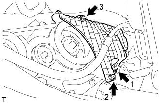
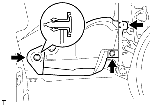
INSTALL NO. 1 ENGINE COVER (w/ No. 1 Engine Cover)
-
Temporarily install the No. 1 engine cover with the 2 bolts and nut.
-
Fully tighten the 2 bolts and nut in the order shown in the illustration.
- Torque:
- 10 N*m { 102 kgf*cm, 7 ft.*lbf }
-
-
INSTALL NO. 1 COOLER COVER (w/ No. 1 Cooler Cover)
-
Temporarily install the No. 1 cooler cover with the 2 nuts.
-
Fully tighten the 2 nuts in the order shown in the illustration.
- Torque:
- 9.8 N*m { 100 kgf*cm, 87 in.*lbf }
-
-
INSTALL NO. 3 ENGINE UNDER COVER
-
Install the No. 3 engine under cover with the 3 clips.
-