CYLINDER BLOCK INSPECTION

-
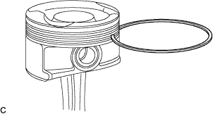
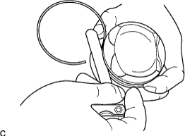
CLEAN PISTON
-
Using an old piston ring or similar device, remove all carbon on each piston.
CAUTION:
Wear protective goggles while servicing.
Note
Do not damage the piston while servicing.
-
Clean all the carbon off each part using solvent.
-
-
INSPECT CYLINDER BLOCK
-
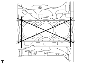
Using a straightedge and feeler gauge, measure the warpage of the contact surface indicated in the illustration.
Maximum warpage 0.05 mm (0.002 in.) If the warpage is greater than the maximum, replace the cylinder block.
-
-
INSPECT CYLINDER BORE
-
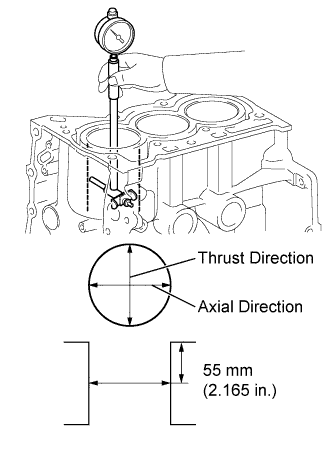
Using a cylinder gauge, measure the cylinder bore diameter in the thrust and axial directions at the position shown in the illustration.
Standard diameter 71.000 to 71.013 mm (2.79527 to 2.79578 in.) Maximum diameter 71.133 mm (2.80051 in.) If the cylinder bore diameter is greater than the maximum, replace the cylinder block.
-
-
INSPECT PISTON
-
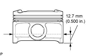
Measure the outer diameter of the piston in the vertical direction to the pin hole, at the point 12.7 mm (0.500 in.) away from the bottom end of the skit.
Piston diameter 70.945 to 70.963 mm (2.79311 to 2.79381 in.) Minimum diameter 70.945 mm (2.79311 in.) If the diameter is not as specified, replace the piston.
-
-
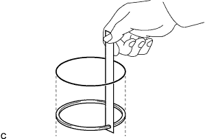
INSPECT PISTON RING GROOVE CLEARANCE
-
Using a feeler gauge, measure the clearance between a new piston ring and the wall of the ring groove.
Standard Ring Groove Clearance Item Specification No. 1 ring 0.02 to 0.07 mm (0.0008 to 0.0028 in.) No. 2 ring 0.02 to 0.06 mm (0.0008 to 0.0024 in.) Oil ring 0.020 to 0.065 mm (0.00079 to 0.00256 in.) If the ring groove clearance is not as specified, replace the piston assembly.
-
-
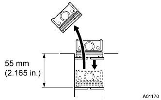
INSPECT PISTON RING END GAP
-
Using a piston, push the piston ring a little beyond the bottom of the ring travel, which is 55 mm (2.165 in.) from the top of the cylinder block.
-
Using a feeler gauge, measure the end gap.
Standard End Gap Item Specification No. 1 ring 0.15 to 0.25 mm (0.0059 to 0.0098 in.) No. 2 ring 0.40 to 0.60 mm (0.0157 to 0.0236 in.) Oil ring 0.10 to 0.40 mm (0.0039 to 0.0157 in.) Maximum End Gap Item Specification No. 1 ring 0.25 mm (0.0098 in.) No. 2 ring 0.60 mm (0.0236 in.) Oil ring 0.40 mm (0.0158 in.)
-
If the end gap is greater than the maximum, replace the piston ring.
-
If the end gap is greater than the maximum, even with a new piston ring, replace the cylinder block.
-
-
-
INSPECT PISTON OIL CLEARANCE
-
Subtract the piston diameter measurement from the cylinder bore diameter measurement to calculate the oil clearance.
Standard oil clearance 0.037 to 0.068 mm (0.00146 to 0.00268 in.) Maximum oil clearance 0.098 mm (0.00386 in.)
-
If the clearance is greater than the maximum, replace all of the piston assemblies.
-
If necessary, replace the cylinder block.
Tech Tips
-
The oil clearance of the piston and cylinder block can be calculated by subtracting the cylinder inner diameter in the thrust direction from the piston outer diameter.
-
Perform the measurement at the point with the most wear because there is joggling wear on the upper end of the piston ring sliding area.
-
-
-
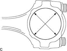
INSPECT CONNECTING ROD SUB-ASSEMBLY
-
Using a cylinder gauge, measure the connecting rod sub-assembly big end diameter, as shown in the illustration.
Standard diameter Mark Specification 1 43.000 to 43.008 mm (1.69291 to 1.69323 in.) 2 43.009 to 43.016 mm (1.69326 to 1.69354 in.) 3 43.017 to 43.024 mm (1.69358 to 1.69386 in.) If the diameter is not as specified, replace the connecting rod.
-
-
INSPECT CONNECTING ROD BOLT
-
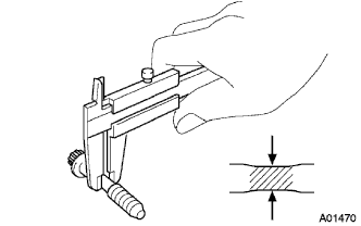
Using a vernier caliper, measure the tension portion.
Minimum diameter 6.4 mm (0.252 in.) If the diameter is less than the minimum, replace the connecting rod bolt.
-
-
INSPECT CONNECTING ROD BEARING
-
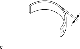
Using a micrometer, measure the thickness of the connecting rod bearing.
Standard thickness 1.492 to 1.501 mm (0.05874 to 0.05909 in.) If the thickness is not as specified, replace the connecting rod bearing.
-
-
INSPECT CONNECTING ROD THRUST CLEARANCE
-
Install the crankshaft with crankshaft journal bearing onto the cylinder block.
-
Install the thrust washer upper.
-
Install the piston with pin into the connecting rod.
-
Install the piston ring onto the piston.
-
Install the connecting rod assembly with connecting rod bearing onto the crankshaft.
-
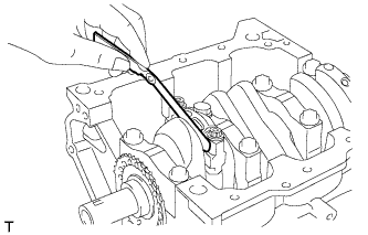
Using a feeler gauge, measure the thrust clearance of the connecting rod.
Standard thrust clearance 0.1 to 0.3 mm (0.004 to 0.012 in.) Maximum thrust clearance 0.36 mm (0.0138 in.)
-
-
INSPECT CONNECTING ROD OIL CLEARANCE
-
Remove the 2 bolts, connecting rod bearing cap and connecting rod bearing.
Note
Arrange the removed parts for each cylinder.
-
Clean the connecting rod bearing and crank pin.
-
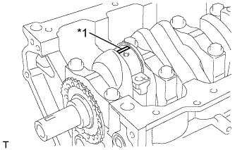
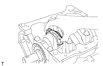
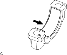
Text in Illustration *1 Plastigage Lay a strip of Plastigage across the crank pin.
-
Apply a light coat of engine oil to the threads and under the heads of the 2 bolts.
-
Tighten the 2 bolts in several passes to the specified torque.
- Torque:
- 15 N*m { 153 kgf*cm, 11 ft.*lbf }
Note
Do not turn the crankshaft.
-
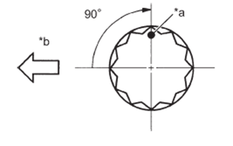
Text in Illustration *a Paint Mark *b Engine Front Mark the front of the 2 bolts with paint.
-
Retighten the 2 bolts by an additional 90° as shown in the illustration.
-
Remove the 2 bolts, then remove the connecting rod bearing cap and connecting rod bearing.
-
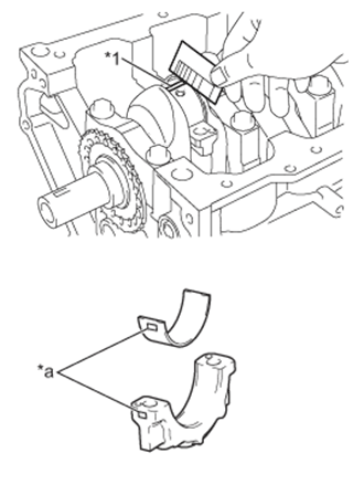
Text in Illustration *1 Plastigage *a Mark Measure the Plastigage at its widest point.
Standard oil clearance 0.010 to 0.036 mm (0.00039 to 0.00142 in.) Maximum oil clearance 0.036 mm (0.00142 in.)
-
If the oil clearance is greater than the maximum, replace the connecting rod bearings. If necessary, inspect the crankshaft.
-
If replacing a bearing, replace it with one that has the same number as its respective connecting rod cap. Each bearing's standard thickness is indicated by mark 1, 2, or 3 on its surface.
Standard Connecting Rod Bearing Cap Bore Diameter Mark Specified Condition 1 43.000 to 43.008 mm (1.69291 to 1.69323 in.) 2 43.008 to 43.016 mm (1.69323 to 1.69355 in.) 3 43.016 to 43.024 mm (1.69355 to 1.69385 in.) Standard Connecting Rod Bearing Thickness Mark Specified Condition 1 1.492 to 1.495 mm (0.05874 to 0.05886 in.) 2 1.495 to 1.498 mm (0.05886 to 0.05898 in.) 3 1.498 to 1.501 mm (0.05898 to 0.05909 in.) Standard Crankshaft Pin Diameter Mark Specified Condition 1, 2, 3 39.992 to 40.000 mm (1.57445 to 1.57480 in.) Note
Completely remove the Plastigage after the measurement.
Tech Tips
The procedures for measuring the connecting rod bearing cap bore diameter and the connecting rod thickness are described in the engine unit inspection section.
-
-
Perform the measurement for the other connecting rod oil clearance using the same procedure.
-
-
INSPECT CRANKSHAFT
-
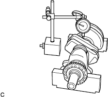
Using a dial indicator and V-blocks, measure the circle runout as shown in the illustration.
Standard circle runout 0.03 mm (0.0012 in.) Maximum circle runout 0.04 mm (0.0016 in.) If the circle runout is greater than the maximum, replace the crankshaft.
Tech Tips
The runout is the half of the value on the indicator when the crankshaft is turned 1 revolution.
-
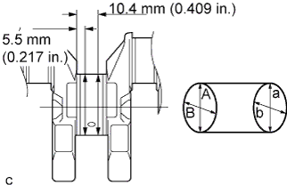
Using a micrometer, measure the diameter of each main journal at the points shown in the illustration.
Diameter 43.988 to 44.000 mm (1.73181 to 1.73228 in.) If the diameter is not as specified, check the crankshaft oil clearance.
-
Check each main journal for elliptic degree and tapered amount as shown.
Maximum elliptic degree and tapered amount 0.03 mm (0.0012 in.) If the elliptic degree or tapered amount is greater than the maximum, replace the crankshaft.
Tech Tips
-
Elliptic degree: A - B or a - b
-
Tapered amount: A - a or B - b
-
-
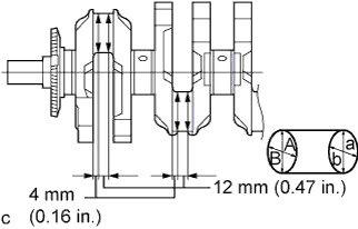
Using a micrometer, measure the diameter of each crankshaft pin at the points shown in the illustration.
Diameter 39.992 to 40.000 mm (1.57449 to 1.57480 in.) If the diameter is not as specified, check the connecting rod oil clearance.
-
Check each crankshaft pin for elliptic degree and tapered amount as shown.
Maximum elliptic degree and tapered amount 0.03 mm (0.0012 in.) If the elliptic degree or tapered amount is greater than the maximum, replace the crankshaft.
Tech Tips
-
Elliptic degree: A - B or a - b
-
Tapered amount: A - a or B - b
-
-
-
INSPECT CRANKSHAFT THRUST CLEARANCE
-
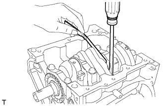
Install the crankshaft with crankshaft bearing onto the cylinder block.
-
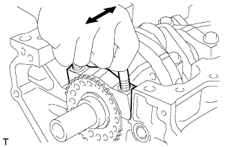
Using a feeler gauge, measure the thrust clearance while prying the crankshaft back and forth with a screwdriver.
Standard clearance 0.02 to 0.04 mm (0.0008 to 0.0016 in.) Maximum clearance 0.30 mm (0.0118 in.) Tech Tips
-
If the thrust clearance is greater than the maximum, replace the thrust washer.
-
If the clearance is still greater than the maximum, replace the crankshaft.
-
-
-
INSPECT CRANKSHAFT OIL CLEARANCE
-
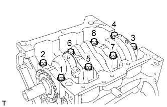
Loosen the 8 bolts in 2 or 3 steps and in the order shown in the illustration.
-
Remove the 8 bolts and the 4 crankshaft bearing caps.
Note
Arrange the removed parts in the removed order.
Tech Tips
-
If it is difficult to remove the crankshaft bearing cap, lightly tap it with a hammer.
-
Move the top of the crankshaft bearing cap back and forth in the axial direction.
-
-
Clean the inner surfaces of the crankshaft bearing and crankshaft bearing cap and the journals of the cylinder block and crankshaft.
-
Check these parts for excessive wear and damage.
-
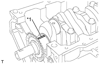
Text in Illustration *1 Plastigage Lay a strip of Plastigage in the axial direction of the crankshaft journal.
-
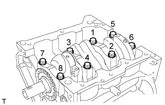
Tighten the 8 bolts in 2 or 3 steps and in the order shown in the illustration.
- Torque:
- 59 N*m { 602 kgf*cm, 44 ft.*lbf }
Note
Do not turn the crankshaft.
-
Remove the 2 bolts, then remove the crankshaft bearing cap and crankshaft bearing.
-
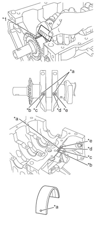
Text in Illustration *1 Plastigage *a Mark *b No. 1 *c No. 2 *d No. 3 *e No. 4 Measure the Plastigage at its widest point.
Standard oil clearance 0.006 to 0.024 mm (0.00024 to 0.00094 in.) Maximum oil clearance 0.024 mm (0.00094 in.)
-
If the oil clearance is greater than the maximum, replace the crankshaft bearing. If necessary, replace the crankshaft.
-
If replacing a bearing, select a new one with the same number. If the number of the bearing cannot be determined, calculate the correct bearing number by adding together the numbers imprinted on the cylinder block and crankshaft. Then select a new bearing with the calculated number according to the chart below. There are 4 sizes of standard bearings, marked "2", "3", "4" and "5" accordingly.
-
EXAMPLE: Cylinder block mark "2" + Crankshaft mark "2" = Use bearing mark "4"
Standard Cylinder Block Journal Bore Diameter Mark Specified Condition 1 48.000 to 48.006 (1.88976 to 1.89000) 2 48.006 to 48.012 (1.89000 to 1.89023) 3 48.012 to 48.018 (1.89023 to 1.890047) Standard Crankshaft Journal Diameter Mark Specified Condition 1 43.994 to 44.000 (1.73204 to 1.73228) 2 43.988 to 43.994 (1.73171 to 1.73204) Standard Bearing Center Wall Thickness Mark Specified Condition 2 1.994 to 1.997 (0.07850 to 0.07862) 3 1.997 to 2.000 (0.07862 to 0.07874) 4 2.000 to 2.003 (0.07874 to 0.07886) 5 2.003 to 2.006 (0.07886 to 0.07898) Note
Completely remove the Plastigage after the measurement.
-
-