SFI SYSTEM, Diagnostic DTC:P0500

| DTC Code | DTC Name |
|---|---|
| P0500 | Vehicle Speed Sensor "A" |
DESCRIPTION
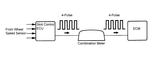
Vehicles, which are equipped with ABS (Anti-lock Brake System), detect the vehicle speed using the skid control ECU (brake actuator assembly) and wheel speed sensor. The wheel speed sensor monitors the wheel rotation speed and sends a signal to the skid control ECU. The skid control ECU converts the wheel speed signal into a 4-pulse signal and transmits it to the ECM via the combination meter. The ECM determines the vehicle speed based on the frequency of the pulse signal.
Tech Tips
-
A voltage of 12 V or 5 V is output from each ECU and then input to the combination meter assembly.
The signal is changed to a pulse signal at the transistor in the combination meter assembly. Each ECU controls the respective system based on the pulse signal.
-
If a short occurs in any of the ECUs or in the wire harness connected to an ECU, all systems using the speed signal will not operate normally.
| DTC No. | DTC Detection Condition | Trouble Area |
|---|---|---|
| P0500 | For Manual Transaxle: While vehicle being driven, no vehicle speed sensor signal to ECM (2 trip detection logic) |
|
| For CVT: Following conditions (a) and (b) met for 2.0 seconds or more (1 trip detection logic): (a) Transmission revolution sensor signal output (NOUT) 1000 rpm or more (b) No vehicle speed sensor signal to ECM |
WIRING DIAGRAM
INSPECTION PROCEDURE
Tech Tips
Read freeze frame data using an intelligent tester. The ECM records vehicle and driving condition information as freeze frame data the moment a DTC is stored. When troubleshooting, freeze frame data can help determine if the vehicle was moving or stationary, if the engine was warmed up or not, if the air-fuel ratio was lean or rich, and other data from the time the malfunction occurred.
PROCEDURE
-
READ VALUE USING INTELLIGENT TESTER (VEHICLE SPEED)
-
Connect an intelligent tester to the DLC3.
-
Turn the ignition switch to ON and turn the tester on.
-
Enter the following menus: Powertrain / Engine and ECT/ Data List / Vehicle Speed.
-
Drive the vehicle.
-
Read the value displayed on the tester.
Result Result Proceed to Values displayed on tester and speedometer display not equal A Values displayed on tester and speedometer display equal B
B 
CHECK FOR INTERMITTENT PROBLEMS Click here
A 
-
-
CHECK COMBINATION METER SYSTEM
-
Inspect the circuits that send vehicle speed signals to this system in the meter system Click here.
-
During inspection for the meter section, if there is an instruction that indicates to go back to inspections for each system, proceed to the next step.
NEXT
-
-
CHECK HARNESS AND CONNECTOR (COMBINATION METER - ECM)
-
Disconnect the combination meter assembly connector.
-
Disconnect the ECM connector.
-
Measure the resistance according to the value(s) in the table below.
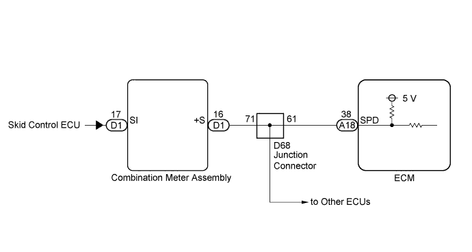
Standard Resistance (Check for Open) Tester Connection Condition Specified Condition D1-16 (+S) - A18-38 (SPD) Always Below 1 Ω -
Reconnect the combination meter assembly connector.
-
Reconnect the ECM connector.
NG 
CHECK HARNESS AND CONNECTOR (ECM - JUNCTION CONNECTOR) Click here
OK 
REPLACE ECM Click here
-
-
CHECK HARNESS AND CONNECTOR (ECM - JUNCTION CONNECTOR)
-
Disconnect the ECM connector.
-
Disconnect the junction connector.
-
Measure the resistance according to the value(s) in the table below.
Standard Resistance (Check for Open) Tester Connection Condition Specified Condition A18-38 (SPD) - D68-61 Always Below 1 Ω -
Reconnect the junction connector.
-
Reconnect the ECM connector.
NG
REPAIR OR REPLACE HARNESS OR CONNECTOR
OK
REPAIR OR REPLACE JUNCTION CONNECTOR
-