SFI SYSTEM, Diagnostic DTC:P0403

| DTC Code | DTC Name |
|---|---|
| P0403 | Exhaust Gas Recirculation Control Circuit |
DESCRIPTION
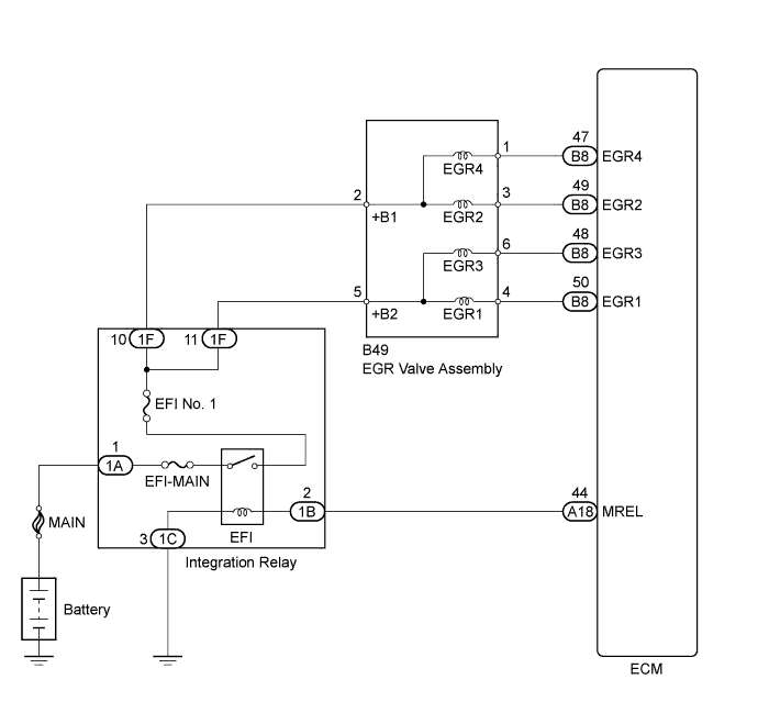
The ECM lowers combustion chamber temperatures and reduces Nitrogen Oxide (NOx) emissions by recirculating an appropriate amount of exhaust gas to the combustion chambers according to the engine operating conditions. When all EGR activation conditions are met (based on sensor signals such as engine speed, coolant temperature, load signal, vehicle speed signal), the ECM turns on the stepper motor inside the EGR valve and linearly controls the opening angle of the EGR valve. When the ECM determines that EGR operation will not influence engine operating conditions, the ECM forcibly opens and closes the EGR valve to monitor changes in manifold pressure. If the manifold pressure change is less than that during normal EGR valve operation, the ECM will detect a shortage of EGR gas flow and set a DTC. Also, an EGR DTC is set if a malfunction (open or short circuit) occurs in the EGR valve operation circuit.
| DTC No. | DTC Detection Condition | Trouble Area |
|---|---|---|
| P0403 | Both of the following conditions are met for 1 second or more (1 trip detection logic):
|
|
WIRING DIAGRAM
INSPECTION PROCEDURE
Note
Inspect the fuses for circuits related to this system before performing the following inspection procedure.
Tech Tips
Read freeze frame data using the intelligent tester. The ECM records vehicle and driving condition information as freeze frame data the moment a DTC is stored. When troubleshooting, freeze frame data can help determine if the vehicle was moving or stationary, if the engine was warmed up or not, if the air fuel ratio was lean or rich, and other data from the time the malfunction occurred.
PROCEDURE
-
INSPECT EGR VALVE ASSEMBLY
-
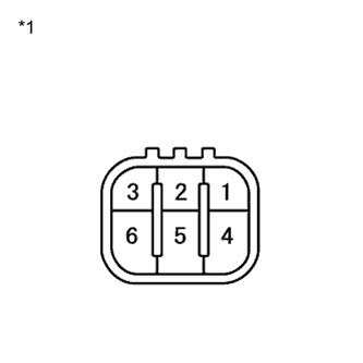
Text in Illustration *1 Component without harness connected
(EGR Valve Assembly)
Disconnect the EGR valve assembly connector.
-
Measure the resistance according to the value(s) in the table below.
Standard Resistance Tester Connection Condition Specified Condition 5 - 6 20°C (68°F) 18 to 22 Ω 5 - 4 20°C (68°F) 18 to 22 Ω 2 - 1 20°C (68°F) 18 to 22 Ω 2 - 3 20°C (68°F) 18 to 22 Ω -
Reconnect the EGR valve assembly connector.
NG 
REPLACE EGR VALVE ASSEMBLY Click here
OK 
-
-
INSPECT EGR VALVE ASSEMBLY (POWER SOURCE VOLTAGE)
-
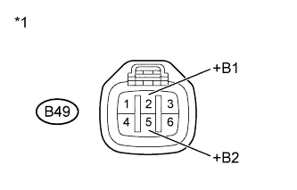
Text in Illustration *1 Front view of wire harness connector
(to EGR Valve Assembly)
Disconnect the EGR valve assembly connector.
-
Turn the ignition switch to ON.
-
Measure the voltage according to the value(s) in the table below.
Standard Voltage Tester Connection Switch Condition Specified Condition B49-2 (+B1) - Body ground Ignition switch ON 11 to 14 V B49-5 (+B2) - Body ground Ignition switch ON 11 to 14 V -
Reconnect the EGR valve assembly connector.
NG 
CHECK HARNESS AND CONNECTOR (EGR VALVE - INTEGRATION RELAY) Click here
OK
-
-
CHECK HARNESS AND CONNECTOR (EGR VALVE - ECM)
-
Disconnect the EGR valve assembly connector.
-
Disconnect the ECM connector.
-
Measure the resistance according to the value(s) in the table below.
Standard Resistance (Check for Open) Tester Connection Condition Specified Condition B49-4 (EGR1) - B8-50 (EGR1) Always Below 1 Ω B49-3 (EGR2) - B8-49 (EGR2) Always Below 1 Ω B49-6 (EGR3) - B8-48 (EGR3) Always Below 1 Ω B49-1 (EGR4) - B8-47 (EGR4) Always Below 1 Ω Standard Resistance (Check for Short) Tester Connection Condition Specified Condition B49-4 (EGR1) or B8-50 (EGR1) - Body ground Always 10 kΩ or higher B49-3 (EGR2) or B8-49 (EGR2) - Body ground Always 10 kΩ or higher B49-6 (EGR3) or B8-48 (EGR3) - Body ground Always 10 kΩ or higher B49-1 (EGR4) or B8-47 (EGR4) - Body ground Always 10 kΩ or higher -
Reconnect the EGR valve assembly connector.
-
Reconnect the ECM connector.
NG
REPAIR OR REPLACE HARNESS OR CONNECTOR
OK 
REPLACE ECM Click here
-
-
CHECK HARNESS AND CONNECTOR (EGR VALVE - INTEGRATION RELAY)
-
Disconnect the EGR valve assembly connector.
-
Remove the integration relay.
-
Measure the resistance according to the value(s) in the table below.
Standard Resistance (Check for Open) Tester Connection Condition Specified Condition B49-2 (+B1) - 1F-10 Always Below 1 Ω B49-5 (+B2) - 1F-11 Always Below 1 Ω Standard Resistance (Check for Short) Tester Connection Condition Specified Condition B49-2 (+B1) or 1F-10 - Body ground Always 10 kΩ or higher B49-5 (+B2) or 1F-11 - Body ground Always 10 kΩ or higher -
Reconnect the EGR valve assembly connector.
-
Reinstall the integration relay.
NG
REPAIR OR REPLACE HARNESS OR CONNECTOR
OK
REPAIR OR REPLACE ECM POWER SOURCE CIRCUIT Click here
-