SFI SYSTEM, Diagnostic DTC:P0014, P0015

| DTC Code | DTC Name |
|---|---|
| P0014 | Camshaft Position "B" - Timing Over-Advanced or System Performance (Bank 1) |
| P0015 | Camshaft Position "B" - Timing Over-Retarded (Bank 1) |
DESCRIPTION
Refer to DTC P0013 Click here.
| DTC No. | DTC Detection Condition | Trouble Area |
|---|---|---|
| P0014 | Valve timing is not adjusted in exhaust valve timing advance range (2 trip detection logic) |
|
| P0015 | Valve timing is not adjusted in exhaust valve timing retard range (1 trip detection logic) |
WIRING DIAGRAM
Refer to DTC P0013 Click here.
INSPECTION PROCEDURE
Tech Tips
Read freeze frame data using the intelligent tester. The ECM records vehicle and driving condition information as freeze frame data the moment a DTC is stored. When troubleshooting, freeze frame data can help determine if the vehicle was moving or stationary, if the engine was warmed up or not, if the air fuel ratio was lean or rich, and other data from the time the malfunction occurred.
PROCEDURE
-
CHECK ANY OTHER DTCS OUTPUT (IN ADDITION TO DTC P0014 OR P0015)
-
Connect the intelligent tester to the DLC3.
-
Turn the ignition switch to ON.
-
Turn the tester on.
-
Enter the following menus: Powertrain / Engine and ECT / DTC.
-
Read the DTCs.
Result Result Proceed to DTC P0014 or P0015 is output A DTC P0014 or P0015 and other DTCs are output B Tech Tips
If any DTCs other than P0014 or P0015 are output, troubleshoot those DTCs first.
B 
GO TO DTC CHART Click here
A 
-
-
PERFORM ACTIVE TEST USING INTELLIGENT TESTER (OPERATE CAMSHAFT TIMING OIL CONTROL VALVE ASSEMBLY)
-
Connect the intelligent tester to the DLC3.
-
Start the engine.
-
Turn the tester on.
-
Turn the A/C switch on.
-
Enter the following menus: Powertrain / Engine and ECT / Active Test / Control the VVT Exhaust Linear (Bank 1).
-
Check the engine speed while operating the camshaft timing oil control valve assembly (for exhaust camshaft) using the tester.
OK Tester Operation Specified Condition 0% (OFF) Normal engine speed 127% (ON) Engine idles roughly or stalls
(soon after camshaft timing oil control valve assembly switched from OFF to ON)
Tech Tips
If the result is not acceptable, cool the engine and perform the Active Test again.
-
Start the engine when the engine coolant temperature is 30°C (86°F) or less.
-
Turn the tester on.
-
Turn the A/C switch on.
-
Enter the following menus: Powertrain / Engine and ECT / Active Test / Control the VVT Exhaust Linear (Bank 1).
-
Check the engine speed while operating the camshaft timing oil control valve assembly (for exhaust camshaft) using the tester when the engine coolant temperature is 50°C (122°F) or less.
OK Tester Operation Specified Condition 0% (OFF) Normal engine speed 127% (ON) Engine idles roughly or stalls
(soon after camshaft timing oil control valve assembly switched from OFF to ON)
-
NG 
CHECK VALVE TIMING (CHECK FOR LOOSE AND JUMPED TOOTH OF TIMING CHAIN) Click here
OK
-
-
CHECK WHETHER DTC OUTPUT RECURS (DTC P0014 OR P0015)
-
Connect the intelligent tester to the DLC3.
-
Turn the ignition switch to ON.
-
Turn the tester on.
-
Clear the DTCs Click here.
-
Start the engine and warm it up.
-
Switch the ECM from normal mode to check mode using the tester Click here.
-
Allow the engine to idle for 3 minutes or more.
-
Drive the vehicle for more than 10 minutes.
-
Enter the following menus: Powertrain / Engine and ECT / DTC.
-
Read the DTCs.
Result Result Proceed to DTC is not output A DTC P0014 or P0015 is output B
B
CHECK VALVE TIMING (CHECK FOR LOOSE AND JUMPED TOOTH OF TIMING CHAIN) Click here
A 
CHECK FOR INTERMITTENT PROBLEMS Click here
-
-
CHECK VALVE TIMING (CHECK FOR LOOSE AND JUMPED TOOTH OF TIMING CHAIN)
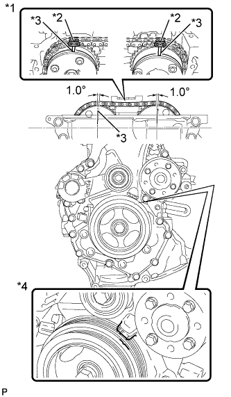
Text in Illustration *1 Reference Camshaft Layout *2 Timing Mark Plate *3 Timing Mark *4 No. 1 Cylinder at TDC Compression
-
Remove the cylinder head cover Click here.
-
Turn the crankshaft pulley, and align its groove with the alignment mark "0" of the timing chain cover.
-
Check that the timing mark of the camshaft timing sprocket is in the position shown in the illustration.
Tech Tips
If not, turn the crankshaft damper 1 revolution (360°) to align the timing mark and sprocket as above.
OK Alignment marks on camshaft timing gears are aligned as shown in the illustration -
Reinstall the cylinder head cover Click here.
NG
ADJUST VALVE TIMING Click here
OK
-
-
INSPECT CAMSHAFT TIMING OIL CONTROL VALVE ASSEMBLY (FOR EXHAUST CAMSHAFT)
-
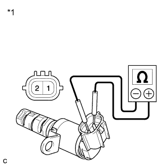
Remove the camshaft timing oil control valve assembly (for exhaust camshaft) Click here.
-
Measure the resistance according to the value(s) in the table below.
Standard Resistance Tester Connection Condition Specified Condition 1 - 2 20°C (68°F) 6.9 to 7.9 Ω Text in Illustration *1 Component without harness connected
(Camshaft Timing Oil Control Valve Assembly (for Exhaust Camshaft))
-
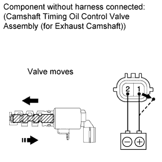
Connect the positive battery terminal to terminal 1 and connect the negative battery terminal to terminal 2. Check valve operation.
OK Valve moves quickly. -
Reinstall the camshaft timing oil control valve assembly (for exhaust camshaft) Click here.
NG
REPLACE CAMSHAFT TIMING OIL CONTROL VALVE ASSEMBLY (FOR EXHAUST CAMSHAFT) Click here
OK
-
-
REPLACE CAMSHAFT BEARING CAP OIL HOLE GASKET (OCV FILTER)
-
Replace the camshaft bearing cap oil hole gasket Click here.
NEXT
-
-
INSPECT CAMSHAFT TIMING GEAR ASSEMBLY (FOR EXHAUST CAMSHAFT)
-
Inspect the camshaft timing gear assembly (for exhaust camshaft) Click here.
NG
REPLACE CAMSHAFT TIMING GEAR ASSEMBLY (FOR EXHAUST CAMSHAFT) Click here
OK
-
-
CHECK WHETHER DTC OUTPUT RECURS (DTC P0014 OR P0015)
-
Connect the intelligent tester to the DLC3.
-
Turn the ignition switch to ON.
-
Turn the tester on.
-
Clear the DTCs Click here.
-
Start the engine and warm it up.
-
Switch the ECM from normal mode to check mode using the tester Click here.
-
Allow the engine to idle for 3 minutes or more.
-
Drive the vehicle for more than 10 minutes.
-
Enter the following menus: Powertrain / Engine and ECT / DTC.
-
Read the DTCs.
Result Result Proceed to DTC is not output A DTC P0014 or P0015 is output B Tech Tips
DTC P0014 or P0015 may be stored when foreign objects in the engine oil are caught in some parts of the system. The DTC will remain stored even if the system returns to normal after a short time. These foreign objects may then be captured by the oil filter.
B
REPLACE ECM Click here
A
END
-