SFI SYSTEM FREEZE FRAME DATA

-
DESCRIPTION
-
The ECM records vehicle and driving condition information as freeze frame data the moment a DTC is stored. When troubleshooting, freeze frame data can be helpful in determining whether the vehicle was running or stopped, whether the air fuel ratio was lean or rich, as well as the other data recorded at the time of a malfunction.
Tech Tips
If it is impossible to duplicate the problem even though a DTC is detected, confirm the freeze frame data.
-
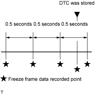
The ECM records engine conditions in the form of freeze frame data every 0.5 seconds. Using the intelligent tester, 5 separate sets of freeze frame data can be checked.
-
3 data sets before the DTC was stored.
-
1 data set when the DTC was stored.
-
1 data set after the DTC was stored.
-
These data sets can be used to duplicate the condition of the vehicle around the time of the occurrence of the malfunction. The data may assist in identifying the cause of the malfunction, and in judging whether it was temporary or not.
-
-
PENDING FREEZE FRAME DATA
Tech Tips
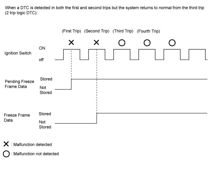
Pending freeze frame data is stored when a 2 trip DTC is first detected during the first trip.
-
Connect the intelligent tester to the DLC3.
-
Turn the ignition switch to ON.
-
Turn the tester on.
-
Enter the following menus: Powertrain / Engine and ECT / DTC.
-
Select a DTC in order to display its pending freeze frame data.
Tech Tips
-
Pending freeze frame data is cleared when any of the following occurs.
-
Using the tester, the DTCs are cleared.
-
The cable is disconnected from the negative (-) battery terminal.
-
40 trips with the engine fully warmed up have been performed after returning to normal. (Pending freeze frame data will not be cleared by only returning the system to normal.)
-
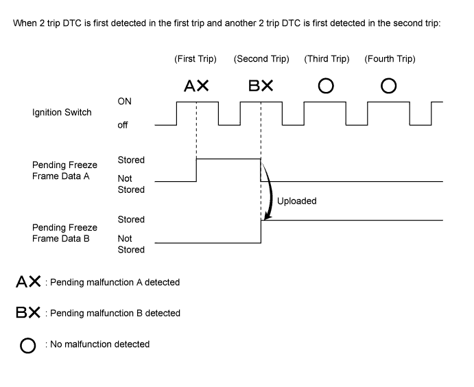
With previous pending freeze frame data stored, if pending freeze frame data is newly stored when a 2 trip DTC is detected in the first trip, the old freeze frame data will be replaced with the new data of the newly detected DTC in the next trip.
-
-
-
LIST OF FREEZE FRAME DATA
Tester Display Measurement Item Diagnostic Note Vehicle Speed Vehicle speed Speed indicated on speedometer Engine Speed Engine speed - Calculate Load Calculated load Calculated load by ECM Vehicle Load Vehicle load Load percentage in terms of maximum intake air flow amount MAF Mass air flow volume If approximately 0.0 gm/s:
-
Mass air flow meter power source circuit open
-
VG circuit open or short
If value 271.0 gm/s or more:
-
E2G circuit open
Atmosphere Pressure Atmospheric pressure - MAP Intake manifold pressure - Coolant Temp Engine coolant temperature If value -40°C (-40°F), sensor circuit open.
If value higher than 140°C (284°F), sensor circuit shorted.
Intake Air Intake air temperature If value -40°C (-40°F), sensor circuit open.
If value higher than 140°C (284°F), sensor circuit shorted.
Engine Run Time Accumulated engine running time - Initial Engine Coolant Temp Engine coolant temperature at engine start - Initial Intake Air Temp Intake air temperature at engine start - Battery Voltage Battery voltage - Glow Indicator Supported*1 Glow indicator supported - Glow Indicator*1 Glow indicator - Accel Sens. No. 1 Volt % Absolute accelerator pedal position No. 1 - Accel Sens. No. 2 Volt % Absolute accelerator pedal position No. 2 - Throttle Sensor Volt % Throttle sensor position Value calculated based on the voltage at terminal VTA1 Throttle Sensor #2 Volt % Throttle sensor position #2 Value calculated based on the voltage at terminal VTA2 Throttle Sensor Position Throttle sensor positioning Recognition value for throttle opening angle on ECM Throttle Motor DUTY Throttle actuator - Throttle Position Throttle valve opening angle Reference:
Check the value when the engine stalls, is difficult to start, or idles roughly.
ISC Flow Flow rate calculated from information from each sensor Reference:
Check the value when the engine stalls, is difficult to start, or idles roughly.
ISC Position Target valve opening angle calculated from ISC control Reference:
Check the value when the engine stalls, is difficult to start, or idles roughly.
ISC Feedback Value ISC feedback value Reference:
Check the value when the engine stalls, is difficult to start, or idles roughly.
ISC Learning Value ISC learning value Reference:
Check the value when the engine stalls, is difficult to start, or idles roughly.
Electric Load Feedback Val Electrical load feedback value Reference:
Check the value when the engine stalls, is difficult to start, or idles roughly.
Air Conditioner FB Val Air conditioner load feedback value Reference:
Check the value when the engine stalls, is difficult to start, or idles roughly.
PS Feedback Val Power steering load feedback value Reference:
Check the value when the engine stalls, is difficult to start, or idles roughly.
Low Revolution Control Status of low engine speed control Reference:
Check the value when the engine stalls, is difficult to start, or idles roughly.
Neutral Control*1 N position control status Reference:
Check the value when the engine stalls, is difficult to start, or idles roughly.
N Range Status*1 Shift lever N status Reference:
Check the value when the engine stalls, is difficult to start, or idles roughly.
Eng Stall Control FB Flow Feedback value of intake air flow Reference:
Check the value when the engine stalls, is difficult to start, or idles roughly.
Deposit Loss Flow Deposit loss air flow rate
-
This value indicates the amount of compensation for a decrease in flow passage area due to the buildup of deposits on the throttle valve.
-
Check this value for reference when the engine stalls, is difficult to start, or idles roughly.
-
When the ISC learned value is initialized by disconnecting the battery negative terminal or removing the fuses (EFI MAIN and ETCS fuses), perform the following procedures in order to quickly relearn the Deposit Loss Flow value. After the Deposit Loss Flow has been relearned, gradual fine adjustments will continue automatically.
-
Start the engine cold and allow the engine to idle.
-
After the engine is warmed up (engine coolant temperature is above 80°C [176°F]), allow the engine to idle for an additional 5 minutes.
-
Turn the ignition switch off and wait for 30 seconds.
-
Start the engine again, and allow the engine to idle for 5 minutes.
Injector (Port) Injection period of No. 1 cylinder - Injection Volum (Cylinder 1) Injection volume - Fuel Pump/Speed Status Fuel pump/speed status - Current Fuel Type Current fuel type Used to identify the current fuel type: Gasoline EVAP (Purge) VSV Purge valve duty ratio - Evap Purge Flow Ratio of evaporative purge flow to intake air volume - Purge Density Learn Value Learning value of purge density - EVAP Purge VSV Purge valve - Purge Cut VSV Duty Purge cut VSV duty - Target Air-Fuel Ratio Ratio compared to stoichiometric level - AF Lambda B1S1 Fuel trim at air fuel ratio sensor (for Bank 1 Sensor 1) - AFS Voltage B1S1 Air fuel ratio sensor output (for Bank 1 Sensor 1) Performing Control the Injection Volume or Control the Injection Volume for A/F Sensor function of Active Test enables the technician to check output voltage of sensor AFS Current B1S1 Air fuel ratio sensor output current (for Bank 1 Sensor 1) Performing Control the Injection Volume or Control the Injection Volume for A/F Sensor function of Active Test enables the technician to check the output current of sensor A/F Heater Duty #1 Air fuel ratio heater duty ratio (for Bank 1) - O2S B1S2 Heated oxygen sensor output (for Bank 1 Sensor 2) Performing Control the Injection Volume or Control the Injection Volume for A/F Sensor function of Active Test enables the technician to check output voltage of sensor O2 Heater B1S2 Heated oxygen sensor heater (for Bank 1 Sensor 2) - O2 Heater Curr Val B1S2 Heated oxygen sensor current (for Bank 1 Sensor 2) - Short FT #1 Short-term fuel trim Short-term fuel compensation used to maintain air fuel ratio at stoichiometric air fuel ratio Long FT #1 Long-term fuel trim
-
Overall fuel compensation carried out in the long term to compensate for a continual deviation of the short-term fuel trim from the central value.
-
Air fuel ratio feedback learning is divided up according to the engine operating range (engine speed x load), and separate values are stored for each operating range. "Long FT #1" indicates the learned value for the current operating range. [A/F Learn Value Idle #1], [A/F Learn Value Low #1], [A/F Learn Value Mid1 #1], [A/F Learn Value Mid2 #1] and [A/F Learn Value High #1] indicate the learned values for the different operating ranges. The learned value that is the same as "Long FT #1" indicates the current engine operating range.
A/F Learn Value Idle #1 Air fuel ratio value area of idle (for Bank 1) - A/F Learn Value Low #1 Air fuel ratio value area of low load (for Bank 1) - A/F Learn Value Mid1 #1 Air fuel ratio value area of middle load 1 (for Bank 1) - A/F Learn Value Mid2 #1 Air fuel ratio value area of middle load 2 (for Bank 1) - A/F Learn Value High #1 Air fuel ratio value area of high load (for Bank 1) - Total FT #1 Total fuel trim (for Bank 1) - Fuel System Status #1 Fuel system status (for Bank 1)
-
OL (Open Loop): Has not yet satisfied conditions to go closed loop
-
CL (Closed Loop): Using air fuel ratio sensor as feedback for fuel control
-
OLDrive: Open loop due to driving conditions (fuel enrichment)
-
OLFault: Open loop due to detected system fault
-
CLFault: Closed loop but air fuel ratio sensor, which is used for fuel control, malfunctioning
Fuel System Status #2 Fuel system status (for Bank 2) Not available IGN Advance Ignition advance - Knock Feedback Value Feedback value of knocking - Knock Correct Learn Value Correction learning value of knocking - Idle Spark Advn Ctrl #1 Ignition timing advance value (for No. 1 cylinder) Reference:
Check the value when the engine stalls, is difficult to start, or idles roughly.
Idle Spark Advn Ctrl #2 Ignition timing advance value (for No. 2 cylinder) Reference:
Check the value when the engine stalls, is difficult to start, or idles roughly.
Idle Spark Advn Ctrl #3 Ignition timing advance value (for No. 3 cylinder) Reference:
Check the value when the engine stalls, is difficult to start, or idles roughly.
Idle Spark Advn Ctrl #4 Ignition timing advance value (for No. 4 cylinder) Reference:
Check the value when the engine stalls, is difficult to start, or idles roughly.
Target EGR Position Target EGR position - EGR Step Position EGR step position - Actual VVT Angle #1 Actual VVT displacement angle (for Bank 1) This item is used for freeze frame data only Actual VVT Ex Angle #1 Actual VVT exhaust displacement angle (for Bank 1) This item is used for freeze frame data only VVT Control Status #1 VVT control status (for Bank 1) - VVT Advance Fail Status of VVT advance fail - Catalyst Temp B1S1 Estimated catalyst temperature (for Bank 1 Sensor 1) - Catalyst Temp B1S2 Estimated catalyst temperature (for Bank 1 Sensor 2) - Starter Signal Starter switch signal - Power Steering Signal Power steering signal - Neutral Position SW Signal*1 Park/neutral position switch signal - Clutch Switch*2 Clutch switch status - Clutch Start SW*2 Clutch start switch status - Stop Light Switch Stop light switch - Shift Indication Enable*2 Shift Indication Enable - A/C Signal Air conditioning signal - Closed Throttle Position SW Closed throttle position switch - Fuel Cut Condition Fuel cut condition - Immobiliser Communication Immobiliser communication - TC Terminal TC terminal status - Time after DTC Cleared Cumulative time after DTC cleared - Distance from DTC Cleared Accumulated distance after DTC cleared - Warmup Cycle Cleared DTC Warm-up cycles since DTCs cleared Number of warm-up cycles since DTCs cleared Dist Batt Cable Disconnect Total distance vehicle driven after battery cable disconnected - IG OFF Elapsed Time Cumulative time after ignition switch off - TC and TE1 TC and TE1 terminals of DLC3 - Ignition Trig. Count Ignition counter - Cylinder #1 Misfire Count Cylinder #1 misfire count - Cylinder #2 Misfire Count Cylinder #2 misfire count - Cylinder #3 Misfire Count Cylinder #3 misfire count - Cylinder #4 Misfire Count Cylinder #4 misfire count - All Cylinders Misfire Count All cylinder misfire count - Misfire RPM Engine speed when misfire occurs - Misfire Load Engine load when misfire occurs - Misfire Margin Margin to detect engine misfire - Catalyst OT MF F/C Catalyst overheat misfire prevention fuel cut function availability Service data Cat OT MF F/C History Catalyst overheat misfire prevention fuel cut function history Service data Cat OT MF F/C Cylinder #1 Display of fuel cut operation in No. 1 cylinder (if certain level of misfire malfunction is detected) - Cat OT MF F/C Cylinder #2 Display of fuel cut operation in No. 2 cylinder (if certain level of misfire malfunction is detected) - Cat OT MF F/C Cylinder #3 Display of fuel cut operation in No. 3 cylinder (if certain level of misfire malfunction is detected) - Cat OT MF F/C Cylinder #4 Display of fuel cut operation in No. 4 cylinder (if certain level of misfire malfunction is detected) - Engine Speed (Starter Off) Engine speed when starter off Reference:
Check the value when the engine stalls, is difficult to start, or idles roughly.
Starter Count Number of times starter turned on after ignition switch turned from off to ON Reference:
Check the value when the engine stalls, is difficult to start, or idles roughly.
Run Dist of Previous Trip Distance traveled during previous trip
-
Run Dist of Previous Trip continues to display the distance traveled in the previous trip during the detection period of DTC P1604, which ends 5 seconds after the engine starts. Then the previous trip distance will be cleared and the distance traveled during this trip, which is calculated based on the vehicle speed, will be displayed.
-
When the engine is difficult to start and DTC P1604 is stored, Run Dist of Previous Trip will continue to be displayed. When inspecting for DTCs other than P1604, or when taking a snapshot, the distance traveled during this trip will be displayed.
Engine Starting Time Time elapsed before engine starts (after starter turns on until engine speed reaches 400 rpm) Reference:
Check the value when the engine stalls, is difficult to start, or idles roughly.
Previous Trip Coolant Temp Coolant temperature of previous trip Reference:
Check the value when the engine stalls, is difficult to start, or idles roughly.
Previous Trip Intake Temp Intake air temperature of previous trip Reference:
Check the value when the engine stalls, is difficult to start, or idles roughly.
Engine Oil Temperature Engine oil temperature (estimated) Reference:
Check the value when the engine stalls, is difficult to start, or idles roughly.
Previous Trip Eng Oil Temp Engine oil temperature of previous trip Reference:
Check the value when the engine stalls, is difficult to start, or idles roughly.
Ambient Temp for A/C Ambient temperature for A/C Reference:
Check the value when the engine stalls, is difficult to start, or idles roughly.
Previous Trip Ambient Temp Ambient temperature of previous trip Reference:
Check the value when the engine stalls, is difficult to start, or idles roughly.
Engine Start Hesitation History of instances of slow engine starts - Low Rev for Eng Start History of low engine speed after engine starts - Minimum Engine Speed Minimum engine speed Reference:
Check the value when the engine stalls, is difficult to start, or idles roughly.
Fuel Cut Elps Time Time elapsed after high engine speed detected Time after the ECM detects a high engine speed (fuel cut speed + 500 rpm or more) Electric Fan Motor Electric fan motor - Brake Override System Brake override system status - Electric Cooling Fan High Electric motor operation status - Electric Cooling Fan Low Electric motor operation status - Idle Fuel Cut Idle fuel cut ON: when throttle valve fully closed and engine speed over 2800 rpm FC TAU Fuel cut with very light load Fuel cut being performed with very light load to prevent incomplete engine combustion Immobiliser Fuel Cut Status of the immobiliser fuel cut - Immobiliser Fuel Cut History Status of the immobiliser fuel cut history - Electrical Load Signal 1 Electrical load signal - Electrical Load Signal 2 Electrical load signal - MT Down Shift Indication*2 MT Down Shift Indication - MT Up Shift Indication*2 MT Up Shift Indication -
-
*1: for CVT
-
*2: for Manual Transaxle
-