SFI SYSTEM, Diagnostic DTC:P0340, P0342, P0343

| DTC Code | DTC Name |
|---|---|
| P0340 | Camshaft Position Sensor Circuit Malfunction |
| P0342 | Camshaft Position Sensor "A" Circuit Low Input (Bank 1 or Single Sensor) |
| P0343 | Camshaft Position Sensor "A" Circuit High Input (Bank 1 or Single Sensor) |
DESCRIPTION
The Camshaft Position (CMP) sensor for the intake camshaft (G signal sensor) consists of a magnet and an MRE element.
The camshaft has a timing rotor for the CMP sensor. When the camshaft rotates, changes occur in the air gaps between the timing rotor and MRE element, which affect the magnetic field. As a result, the resistance of the MRE material fluctuates. The CMP sensor converts the camshaft rotation data to pulse signals, and uses the pulse signals to determine the camshaft angle, which it sends to the ECM. Then the ECM uses this data to control ignition and fuel injection timing.
| DTC No. | DTC Detection Condition | Trouble Area |
|---|---|---|
| P0340 | No camshaft position sensor signal to ECM while cranking (2 trip detection logic) |
|
| Missing camshaft position sensor signal despite crankshaft position sensor inputs normal at engine speed of 600 rpm or more* (1 trip detection logic) |
||
| P0342 | Output voltage of camshaft position sensor less than 0.3 V for 4 seconds (1 trip detection logic) |
|
| P0343 | Output voltage of camshaft position sensor 4.7 V or more for 4 seconds (1 trip detection logic) |
|
*: for Manual Transaxle
When the engine is stopped due to Stop and Start system control, the camshaft position sensor does not monitor, but will resume monitoring when the engine is running.
-
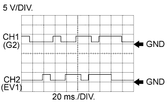
Reference: Inspection using an oscilloscope.
Tech Tips
-
The correct waveform is as shown.
-
G2 stands for the camshaft position sensor signal (for intake camshaft), and EV1 stands for the camshaft position sensor signal (for exhaust camshaft).
-
Grounding failure of the shielded wire may cause a noisy waveform.
Item Content Terminals CH1: G2+ - G2-
CH2: EV1+ - EV1-
Equipment Settings 5 V/DIV.
20 ms./DIV.
Conditions Idling with warm engine -
WIRING DIAGRAM
Refer to DTC P0335 Click here.
INSPECTION PROCEDURE
Tech Tips
-
If no problem is found through this diagnostic troubleshooting procedure, troubleshoot the engine mechanical system.
-
Read freeze frame data using the intelligent tester. The ECM records vehicle and driving condition information as freeze frame data the moment a DTC is stored. When troubleshooting, freeze frame data can help determine if the vehicle was moving or stationary, if the engine was warmed up or not, if the air fuel ratio was lean or rich, and other data from the time the malfunction occurred.
PROCEDURE
-
CHECK ANY OTHER DTCS OUTPUT (IN ADDITION TO DTC P0340, P0342 OR P0343)
-
Connect the intelligent tester to the DLC3.
-
Turn the ignition switch to ON.
-
Turn the tester on.
-
Enter the following menus: Powertrain / Engine and ECT / DTC.
-
Read DTCs.
Result Result Proceed to DTC P0340, P0342 or P0343 is output A DTC P0340, P0342 or P0343 and other DTCs are output B Tech Tips
If any DTCs other than P0340, P0342 or P0343 are output, troubleshoot those DTCs first.
B 
GO TO DTC CHART Click here
A 
-
-
INSPECT CAMSHAFT POSITION SENSOR (FOR INTAKE CAMSHAFT) (SENSOR POWER SOURCE)
-
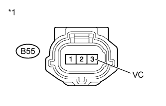
Text in Illustration *1 Front view of wire harness connector
(to Camshaft Position Sensor for Intake Camshaft)
Disconnect the camshaft position sensor (for intake camshaft) connector.
-
Turn the ignition switch to ON.
-
Measure the voltage according to the value(s) in the table below.
Standard Voltage Tester Connection Switch Condition Specified Condition B55-3 (VC) - Body ground Ignition switch ON 4.5 to 5.5 V -
Reconnect the camshaft position sensor (for intake camshaft) connector.
NG 
CHECK HARNESS AND CONNECTOR (CAMSHAFT POSITION SENSOR - ECM) Click here
OK
-
-
CHECK HARNESS AND CONNECTOR (CAMSHAFT POSITION SENSOR FOR INTAKE CAMSHAFT - ECM)
-
Disconnect the camshaft position sensor (for intake camshaft) connector.
-
Disconnect the ECM connector.
-
Measure the resistance according to the value(s) in the table below.
Standard Resistance (Check for Open) Tester Connection Condition Specified Condition B55-1 (VVI+) - B8-94 (G2+) Always Below 1 Ω B55-2 (VVI-) - B8-118 (G2-) Always Below 1 Ω Standard Resistance (Check for Short) Tester Connection Condition Specified Condition B55-1 (VVI+) or B8-94 (G2+) - Body ground Always 10 kΩ or higher B55-2 (VVI-) or B8-118 (G2-) - Body ground Always 10 kΩ or higher -
Reconnect the camshaft position sensor (for intake camshaft) connector.
-
Reconnect the ECM connector.
NG
REPAIR OR REPLACE HARNESS OR CONNECTOR
OK
-
-
CHECK SENSOR INSTALLATION (CAMSHAFT POSITION SENSOR FOR INTAKE CAMSHAFT)
-
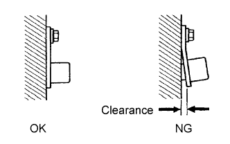
Check the camshaft position sensor (for intake camshaft) installation.
OK Sensor is installed correctly.
NG
SECURELY REINSTALL CAMSHAFT POSITION SENSOR FOR INTAKE CAMSHAFT
OK
-
-
INSPECT CAMSHAFT (TIMING ROTOR)
-
Check the timing rotor of the intake camshaft.
OK Camshaft timing rotor does not have any cracks or deformation.
NG
REPLACE CAMSHAFT Click here
OK
-
-
REPLACE CAMSHAFT POSITION SENSOR (FOR INTAKE CAMSHAFT)
-
Replace the camshaft position sensor for intake camshaft Click here.
NEXT
-
-
CHECK WHETHER DTC OUTPUT RECURS (DTC P0340, P0342 OR P0343)
-
Connect the intelligent tester to the DLC3.
-
Turn the ignition switch to ON.
-
Turn the tester on.
-
Clear the DTCs Click here.
-
Switch the ECM from normal mode to check mode Click here.
-
Start the engine and allow the engine to idle for 10 seconds or more.
-
Enter the following menus: Powertrain / Engine and ECT / DTC.
-
Read DTCs.
Result Result Proceed to DTC P0340, P0342 or P0343 is output A DTC is not output B Tech Tips
If the engine does not start, replace the ECM.
B
END
A
-
-
CHECK VALVE TIMING
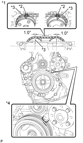
Text in Illustration *1 Reference Camshaft Layout *2 Timing Mark Plate *3 Timing Mark *4 No. 1 Cylinder at TDC Compression
-
Remove the cylinder head cover Click here.
-
Turn the crankshaft pulley, and align its groove with the alignment mark "0" of the timing chain cover.
-
Check that the timing mark of the camshaft timing sprocket is in the position shown in the illustration.
Tech Tips
If not, turn the crankshaft damper 1 revolution (360°) to align the timing mark and sprocket as above.
OK Alignment marks on camshaft timing gears are aligned as shown in the illustration -
Reinstall the cylinder head cover Click here.
NG
ADJUST VALVE TIMING
OK
-
-
CHECK WHETHER DTC OUTPUT RECURS (DTC P0340, P0342 OR P0343)
-
Connect the intelligent tester to the DLC3.
-
Turn the ignition switch to ON.
-
Turn the tester on.
-
Clear the DTCs Click here.
-
Switch the ECM from normal mode to check mode Click here.
-
Start the engine and allow the engine to idle for 10 seconds or more.
-
Enter the following menus: Powertrain / Engine and ECT / Trouble codes.
-
Read DTCs.
Result Result Proceed to DTC is not output A DTC P0340, P0342 or P0343 is output B Tech Tips
If the engine does not start, replace the ECM.
B
REPLACE ECM Click here
A 
END
-
-
CHECK HARNESS AND CONNECTOR (CAMSHAFT POSITION SENSOR - ECM)
-
Disconnect the camshaft position sensor (for intake camshaft) connector.
-
Disconnect the ECM connector.
-
Measure the resistance according to the value(s) in the table below.
Standard Resistance (Check for Open) Tester Connection Condition Specified Condition B55-3 (VC) - B8-119 (VCV1) Always Below 1 Ω Standard Resistance (Check for Short) Tester Connection Condition Specified Condition B55-3 (VC) or B8-119 (VCV1) - Body ground Always 10 kΩ or higher -
Reconnect the camshaft position sensor (for intake camshaft) connector.
-
Reconnect the ECM connector.
NG
REPAIR OR REPLACE HARNESS OR CONNECTOR
OK
REPLACE ECM Click here
-