ECD SYSTEM, Diagnostic DTC:P2080, P2084

| DTC Code | DTC Name |
|---|---|
| P2080 | Exhaust Gas Temperature Sensor Circuit Range/Performance Bank 1 Sensor 1 |
| P2084 | Exhaust Gas Temperature Sensor Circuit Range/Performance Bank 1 Sensor 2 |
DESCRIPTION
Refer to DTC P0545 Click here.
| DTC Detection Drive Pattern | DTC Detection Condition | Trouble Area |
|---|---|---|
| 5 minutes elapsed after engine start | The actual exhaust gas temperature sensor B1S1 output differs from the estimate exhaust gas temperature sensor more than threshold for 8 seconds or more. (1 trip detection logic) |
|
| DTC Detection Drive Pattern | DTC Detection Condition | Trouble Area |
|---|---|---|
| 5 minutes elapsed after engine start | The actual exhaust gas temperature sensor B1S2 output differs from the estimate exhaust gas temperature sensor more than threshold for 8 seconds or more. (1 trip detection logic) |
|
| DTC No. | Data List |
|---|---|
| P2080 |
|
| P2084 |
Tech Tips
-
Sensor 1 represents a sensor located before the CCo catalytic converter.
-
Sensor 2 represents a sensor located before the DPF catalytic converter.
-
If DTC P2080 and/or P2084 is stored, the following symptoms may appear:
-
White smoke
MONITOR DESCRIPTION
When the vehicle is being driven, the ECM monitors the exhaust gas temperature comparing between the estimate and the actual temperature based on the values of the exhaust gas temperature sensors B1S1 and B1S2. If the difference between the estimate and the actual temperature is more than the threshold, the ECM interprets this as a malfunction in the exhaust gas temperature sensor and stores DTCs.
WIRING DIAGRAM
Refer to DTC P0545 Click here and DTC P0548 Click here.
INSPECTION PROCEDURE
Note
When replacing the ECM and/or fuel injector, the ECM needs Registration and Initialization Click here.
Tech Tips
-
When the ECM must be replaced, before replacing the ECM, perform the "Learning Values Save" function using the intelligent tester. Then after installing the new ECM, perform all of the initializations/registrations for the "Learning Values Write" function by following the instructions shown on the tester display.
-
Read freeze frame data using the intelligent tester. Freeze frame data records the engine condition when malfunctions are detected. When troubleshooting, freeze frame data can help determine if the vehicle was moving or stationary, if the engine was warmed up or not, and other data from the time the malfunction occurred.
PROCEDURE
-
CHECK ANY OTHER DTCS OUTPUT (IN ADDITION TO DTC P2080 AND P2084)
-
Connect the intelligent tester to the DLC3.
-
Turn the ignition switch to ON and turn the tester on.
-
Enter the following menus: Powertrain / Engine and ECT / DTC.
-
Read DTCs.
Result Result Proceed to P2080 and/or P2084 and P0545, P0546, P0548 and/or P0549 A Except above B Tech Tips
If DTCs related to open/short circuit of exhaust gas temperature sensor other than P2080 and/or P2084 are output, perform troubleshooting for those DTCs first.
B 
CHECK HARNESS AND CONNECTOR (EXHAUST GAS TEMPERATURE SENSOR - ECM) Click here
A 
GO TO DTC CHART Click here
-
-
CHECK HARNESS AND CONNECTOR (EXHAUST GAS TEMPERATURE SENSOR - ECM)
-
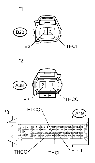
*1 Front view of wire harness connector
(to Exhaust Gas Temperature Sensor B1S1)
*2 Front view of wire harness connector
(to Exhaust Gas Temperature Sensor B1S2)
*3 Front view of wire harness connector
(to ECM)
Disconnect the exhaust gas temperature sensor connector.
-
Disconnect the ECM connector.
-
Measure the resistance according to the value(s) in the table below.
Standard Resistance (Check for Open) Tester Connection Condition Specified Condition B22-2 (THCI) - A19-50 (THCI) Always Below 1 Ω B22-1 (E2) - A19-51 (ETCI) Always Below 1 Ω A38-1 (THCO) - A19-48 (THCO) Always Below 1 Ω A38-2 (E2) - A19-49 (ETCO) Always Below 1 Ω Standard Resistance (Check for Short) Tester Connection Condition Specified Condition B22-2 (THCI) or A19-50 (THCI) - Body ground Always 10 kΩ or higher B22-1 (E2) or A19-51 (ETCI) - Body ground Always 10 kΩ or higher A38-1 (THCO) or A19-48 (THCO) - Body ground Always 10 kΩ or higher A38-2 (E2) or A19-49 (ETCO) - Body ground Always 10 kΩ or higher -
Reconnect the exhaust gas temperature sensor connector.
-
Reconnect the ECM connector.
NG
REPAIR OR REPLACE HARNESS OR CONNECTOR Click here
OK 
-
-
READ VALUE USING INTELLIGENT TESTER (EXHAUST TEMPERATURE B1S1 AND B1S2)
-
Stop the engine and wait for 30 seconds or more.
-
Start the engine.
-
Allow the engine to idle for 5 minutes.
-
Connect the intelligent tester to the DLC3.
-
Turn the tester on.
-
Enter the following menus: Powertrain / Engine and ECT / Data List / Exhaust Temperature B1S1 and Exhaust Temperature B1S2.
-
Read the values.
Note
Confirm the PM regeneration is not operating.
Tech Tips
When reading the values of Data List, confirm that PM regeneration is not activating (value of "After Injection Period" is 0) by entering the following menus: Powertrain / Engine and ECT / Data List / After Injection Period.
If PM regeneration is activating (value of "After Injection Period" is not 0), drive the vehicle until the PM regeneration is complete (value of "After Injection Period" becomes 0).
Standard Exhaust Temperature B1S1 and Exhaust Temperature B1S2 display between 80 to 300°C (176 to 572°F). Difference between Exhaust Temperature B1S1 and Exhaust Temperature B1S2 should be within +/-100°C (212°F). Tech Tips
For reference, the results of a "real-vehicle check" are as shown in the table below:
Note
In the table below, the values listed are reference. Do not depend solely on these reference values when deciding whether a part is faulty or not.
Exhaust Temperature B1S1 and B1S2 (Result of Real-Vehicle Check) Condition Exhaust Temperature B1S1 Exhaust Temperature B1S2 Idling with warmed engine 109°C (228°F) 106°C (223°F) 3010 rpm without load 154°C (309°F) 136°C (277°F) 4508 rpm without load 204°C (399°F) 184°C (363°F)
NG
REPLACE EXHAUST GAS TEMPERATURE SENSOR Click here
OK
-
-
PERFORM ACTIVE TEST USING INTELLIGENT TESTER (CONTROL THE EGR STEP POSITION)
-
Remove the electric EGR valve assembly Click here.
-
Connect the electric EGR valve assembly connector.
-
Connect the intelligent tester to the DLC3.
-
Turn the ignition switch to ON and turn the tester on.
-
Enter the following menus: Powertrain / Engine and ECT / Active Test / Control the EGR Step Position / Data List / Actual EGR Valve Pos.
-
When changing the Active Test value from 0 to 100%, check that Actual EGR Valve Pos. smoothly changes to the set opening angle.
OK Value smoothly changes to the set opening angle. -
Check that the EGR valve is fully closed.
OK The EGR valve fully closes. 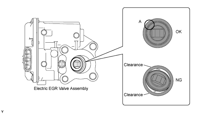
Note
When cleaning the electric EGR control valve, use a piece of cloth. Spraying the solvent directly onto these parts or soaking the parts in the solvent may damage the parts.
Tech Tips
-
Hold the EGR valve to a light and confirm that the valve contacts with the valve seat securely.
-
If light leaks out from the valve, the EGR valve is not fully closed.
-
If the EGR valve cannot close fully, hesitation or poor acceleration almost certainly has occurred while driving the vehicle.
-
Even if the EGR valve is closed completely, light leaks from the closed gap of valve seat (A part) as shown in the illustration, but this is normal.
-
OK
REMOVE DEPOSIT (CLEAN EGR PASSAGE) Click here
NG
REPLACE ELECTRIC EGR CONTROL VALVE ASSEMBLY Click here
-
-
REPLACE ELECTRIC EGR CONTROL VALVE ASSEMBLY
-
Replace the electric EGR valve assembly Click here.
-
Turn the ignition switch to ON.
-
Turn the ignition switch off and wait for 30 seconds or more.
NEXT
-
-
REMOVE DEPOSIT (CLEAN EGR PASSAGE)
-
Remove the electric EGR valve assembly, diesel throttle body assembly, intake air connector and EGR pipe connector.
-
Remove the deposits from those parts and clean them.
Note
-
When cleaning the EGR valve and the diesel throttle body, use a piece of cloth. Spraying the solvent directly onto these parts or soaking the parts in the solvent may damage the parts.
-
Extreme care must be taken to prevent the removed deposits from falling into the engine unit during cleaning.
Tech Tips
-
Remove the intake manifold from the cylinder head when it has to be cleaned.
-
Do not leave any deposits in the EGR valve assembly when cleaning the valve.
-
-
Reinstall the electric EGR valve assembly, diesel throttle body assembly, intake air connector and EGR pipe connector.
NEXT
-
-
READ VALUE USING INTELLIGENT TESTER (INJECTION FEEDBACK VAL #1 TO #4 AND INJECTION VOLUME)
-
Start the engine and warm it up until the engine coolant temperature reaches 75°C (167°F) or more.
-
Allow the engine to idle for 30 seconds or more.
Tech Tips
The shift lever should be in N and the A/C switch and all accessory switches should be off.
-
Connect the intelligent tester to the DLC3.
-
Turn the tester on.
-
Enter the following menus: Powertrain / Engine and ECT / Data List / Injection Feedback Val. #1 to #4 and Injection Volume.
-
Read the values.
Tech Tips
When reading the values of Data List, confirm that PM regeneration is not activating (value of "After Injection Period" is 0) by entering the following menus: Powertrain / Engine and ECT / Data List / After Injection Period.
If PM regeneration is activating (value of "After Injection Period" is not 0), drive the vehicle until the PM regeneration is complete (value of "After Injection Period" becomes 0).
Standard Tester Display Engine Condition Specified Condition Injection Volume Idling Less than 8 mm3/st
Injection Feedback Val. #1
Injection Feedback Val. #2
Injection Feedback Val. #3
Injection Feedback Val. #4
Idling Between -2.0 mm3/st and 2.0 mm3
Tech Tips
-
Cylinders that have a compensation value which is more than the value specified above are considered to be faulty. Use the following steps to inspect and repair the cylinder.
-
If the value of Injection Volume is 8 mm3/st or more and the value of all of the Injector Feedback Val. #1 to #4 is within the threshold, replace the fuel injectors for all cylinders.
In this case, there is a possibility that too much recirculated exhaust gas enters into the engine. Therefore, you should compare the Target EGR Position with the Actual EGR Valve Pos. by entering the following menus using the intelligent tester: Powertrain / Engine and ECT / Data List / Target EGR Position and Actual EGR Valve Pos.
If the difference between Target EGR Position and Actual EGR Valve Pos. exceeds +/-10%, the EGR system may have a malfunction.
-
OK
CHECK WHETHER DTC OUTPUT RECURS (DTC P2080 OR P2084) Click here
NG
PERFORM ACTIVE TEST USING INTELLIGENT TESTER (INJECTION CUT FOR IDENTIFYING MALFUNCTIONING CYLINDER) Click here
-
-
REPAIR OR REPLACE HARNESS OR CONNECTOR
NEXT
CHECK WHETHER DTC OUTPUT RECURS (DTC P2080 OR P2084) Click here
-
REPLACE EXHAUST GAS TEMPERATURE SENSOR
-
Replace the malfunctioning exhaust gas temperature sensor B1S1 or B1S2 Click here.
NEXT
CHECK WHETHER DTC OUTPUT RECURS (DTC P2080 OR P2084) Click here
-
-
PERFORM ACTIVE TEST USING INTELLIGENT TESTER (INJECTION CUT FOR IDENTIFYING MALFUNCTIONING CYLINDER)
-
Start the engine and warm it up until the engine coolant temperature reaches 75°C (167°F) or more.
-
Connect the intelligent tester to the DLC3.
-
Turn the tester on.
-
Enter the following menus: Powertrain / Engine and ECT / Active Test / Control the Cylinder#1 to #4 Fuel Cut.
-
Check the four cylinders in sequence to identify a faulty cylinder.
Tech Tips
-
DTCs may be output after this Active Test. Make sure to check for DTCs after this Active Test. If any DTCs are output, make sure to clear them Click here.
-
If the engine idling condition does not change despite cutting off the fuel injection, the cylinder is malfunctioning.
-
NEXT
-
-
PERFORM ACTIVE TEST USING INTELLIGENT TESTER (INJECTION CUT FOR IDENTIFYING MALFUNCTIONING PART)
-
Change the fuel injector of the malfunctioning cylinder to a fuel injector of the cylinder that functions normally.
-
Start the engine and drive the vehicle until the engine coolant temperature reaches 75°C (167°F) or more.
-
Connect the intelligent tester to the DLC3.
-
Turn the tester on.
-
Enter the following menus: Powertrain / Engine and ECT / Active Test / Control the Cylinder#1 to #4 Fuel Cut.
-
Check the four cylinders in sequence to identify a faulty cylinder.
Tech Tips
-
DTCs may be output after this Active Test. Make sure to check for DTCs after this Active Test. If any DTCs are output, make sure to clear them Click here.
-
If the engine idling condition does not change despite cutting off the fuel injection, the cylinder is malfunctioning.
-
-
Confirm the malfunctioning cylinder.
Result Result Proceed to Different cylinder malfunction identified A Same cylinder malfunction identified B
B
CHECK ENGINE ASSEMBLY Click here
A
-
-
REPLACE FUEL INJECTOR ASSEMBLY
-
Replace the fuel injector of the malfunctioning cylinder Click here.
NEXT
-
-
PERFORM REGISTRATION AND INITIALIZATION
-
Perform registration and initialization Click here.
NEXT
-
-
BLEED AIR FROM FUEL SYSTEM
-
Bleed air from fuel system Click here.
NEXT
CHECK WHETHER DTC OUTPUT RECURS (DTC P2080 OR P2084) Click here
-
-
CHECK ENGINE ASSEMBLY
-
Check the engine assembly to determine the cause of low compression and other factors that would cause the exhaust gas temperature to rise insufficiently.
Tech Tips
The speed of each cylinder can be measured (compression test) by using the intelligent tester.
In the compression test, need to disconnect the injector connectors of all cylinders, and crank the engine for approximately 10 seconds. At this time, the speed of each cylinder is measured. If the speed of one cylinder is higher than the other cylinders, the compression pressure of that cylinder is determined to be lower than the other cylinders.
-
Warm up the engine.
-
Turn the ignition switch off and disconnect the injector connectors of all cylinders.
-
Connect the intelligent tester to the DLC3.
-
Turn the ignition switch to ON and turn the tester on.
-
Enter the following menus: Powertrain / Engine and ECT / Data List / Engine Speed of Cyl #1, Engine Speed of Cyl #2, Engine Speed of Cyl #3, Engine Speed of Cyl #4 and Av Engine Speed of All Cyl.
-
Crank the engine for about 10 seconds.
Note
-
Do not crank the engine for more than 20 seconds.
-
Use a fully-charged battery.
-
-
Read the engine speed (Engine Speed of Cyl #1 to #4, Av Engine Speed of All Cyl) displayed on the tester when the ignition switch is ON.
Tech Tips
Do not turn the ignition switch off when finish the cranking.
-
Reconnect the injector connectors of all cylinders.
-
Clear the DTCs.
-
NEXT
-
-
CHECK WHETHER DTC OUTPUT RECURS (DTC P2080 OR P2084)
-
Connect the intelligent tester to the DLC3.
-
Turn the ignition switch to ON and turn the tester on.
-
Clear the DTCs Click here.
-
Start the engine.
-
Allow the engine to idle for 7 minutes or more.
-
Enter the following menus: Powertrain / Engine and ECT / DTC.
-
Read the DTCs.
Result Result Proceed to DTC P2080 or P2084 A No DTC output B
B 
END
A
-
-
REPLACE ECM
-
Replace the ECM Click here.
NEXT
-
-
CONFIRM WHETHER MALFUNCTION HAS BEEN SUCCESSFULLY REPAIRED
-
Connect the intelligent tester to the DLC3.
-
Turn the ignition switch to ON and turn the tester on.
-
Clear the DTCs Click here.
-
Start the engine.
-
Allow the engine to idle for 7 minutes or more.
-
Enter the following menus: Powertrain / Engine and ECT / DTC.
-
Confirm that the DTC is not output again.
NEXT
END
-