ECD SYSTEM, Diagnostic DTC:P1271

| DTC Code | DTC Name |
|---|---|
| P1271 | Fuel Regulator Circuit Malfunction (EDU Drive) |
DESCRIPTION
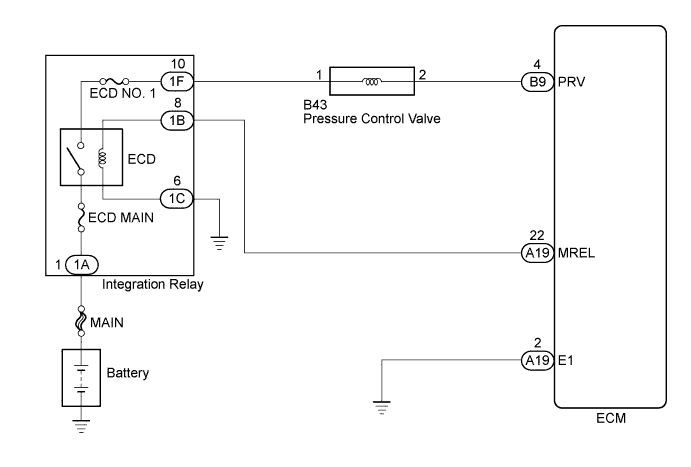
Based on signals from the ECM, the pressure control valve opens when sudden deceleration occurs or when the ignition switch is turned off, to prevent the fuel pressure from becoming too high.
| DTC Detection Drive Pattern | DTC Detection Condition | Trouble Area |
|---|---|---|
| Ignition switch ON for 1 second | Open or short in pressure control valve circuit. (1 trip detection logic) |
|
Tech Tips
When the fuel temperature is less than 10°C (50°F), both the pressure control valve and fuel metering unit act in union for control the fuel pressure to the target fuel pressure.
WIRING DIAGRAM
INSPECTION PROCEDURE
Note
-
When replacing the ECM, the ECM needs Registration and Initialization Click here.
-
Inspect the fuses for circuits related to this system before performing the following inspection procedure.
Tech Tips
-
When the ECM must be replaced, before replacing the ECM, perform the "Learning Values Save" function using the intelligent tester. Then after installing the new ECM, perform all of the initializations/registrations for the "Learning Values Write" function by following the instructions shown on the tester display.
-
Read freeze frame data using the intelligent tester. Freeze frame data records the engine condition when malfunctions are detected. When troubleshooting, freeze frame data can help determine if the vehicle was moving or stationary, if the engine was warmed up or not, and other data from the time the malfunction occurred.
PROCEDURE
-
INSPECT COMMON RAIL ASSEMBLY (PRESSURE CONTROL VALVE)
-
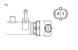
Text in Illustration *1 Component without harness connected
(Pressure Control Valve)
Disconnect the pressure control valve connector.
-
Measure the resistance according to the value(s) in the table below.
Standard Resistance Tester Connection Condition Specified Condition 1 - 2 20°C (68°F) 3.42 to 3.78 Ω -
Reconnect the pressure control valve connector.
NG 
REPLACE COMMON RAIL ASSEMBLY Click here
OK 
-
-
CHECK HARNESS AND CONNECTOR (PRESSURE CONTROL VALVE - ECM)
-
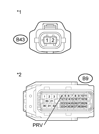
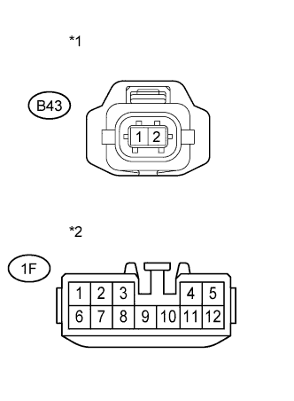
Text in Illustration *1 Front view of wire harness connector
(to Pressure Control Valve)
*2 Front view of wire harness connector
(to ECM)
Disconnect the pressure control valve connector.
-
Disconnect the ECM connector.
-
Measure the resistance according to the value(s) in the table below.
Standard Resistance (Check for Open) Tester Connection Condition Specified Condition B43-2 - B9-4 (PRV) Always Below 1 Ω Standard Resistance (Check for Short) Tester Connection Condition Specified Condition B43-2 or B9-4 (PRV) - Body ground Always 10 kΩ or higher -
Reconnect the pressure control valve connector.
-
Reconnect the ECM connector.
NG
REPAIR OR REPLACE HARNESS OR CONNECTOR Click here
OK
-
-
CHECK HARNESS AND CONNECTOR (POWER SOURCE)
-
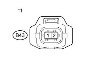
Text in Illustration *1 Front view of wire harness connector
(to Pressure Control Valve)
Disconnect the pressure control valve connector.
-
Measure the voltage according to the value(s) in the table below.
Standard Voltage Tester Connection Switch Condition Specified Condition B43-1 - Body ground Ignition switch ON 11 to 14 V -
Reconnect the pressure control valve connector.
NG
CHECK HARNESS AND CONNECTOR (PRESSURE CONTROL VALVE - INTEGRATION RELAY) Click here
OK
-
-
CHECK WHETHER DTC OUTPUT RECURS
-
Connect the intelligent tester to the DLC3.
-
Clear the DTCs Click here.
-
Turn the ignition switch off and wait for 30 seconds or more.
-
Turn the ignition switch to ON and wait for 1 second or more.
-
Enter the following menus: Powertrain / Engine and ECT / DTC.
-
Read the DTCs.
Result Result Proceed to No DTC output A DTC P1271 B
B
REPLACE ECM Click here
A 
CHECK FOR INTERMITTENT PROBLEMS Click here
-
-
REPLACE ECM
-
Replace the ECM Click here.
NEXT
CONFIRM WHETHER MALFUNCTION HAS BEEN SUCCESSFULLY REPAIRED Click here
-
-
CHECK HARNESS AND CONNECTOR (PRESSURE CONTROL VALVE - INTEGRATION RELAY)
-
Text in Illustration *1 Front view of wire harness connector
(to Pressure Control Valve)
*2 Front view of wire harness connector
(to Integration Relay)
Disconnect the pressure control valve connector.
-
Disconnect the integration relay connector.
-
Measure the resistance according to the value(s) in the table below.
Standard Resistance (Check for Open) Tester Connection Condition Specified Condition B43-1 - 1F-10 Always Below 1 Ω Standard Resistance (Check for Short) Tester Connection Condition Specified Condition B43-1 or 1F-10 - Body ground Always 10 kΩ or higher -
Reconnect the pressure control valve connector.
-
Reconnect the integration relay connector.
NG
REPAIR OR REPLACE HARNESS OR CONNECTOR Click here
OK
-
-
CHECK ECM POWER SOURCE CIRCUIT
-
Check ECM power source circuit Click here.
NEXT
CONFIRM WHETHER MALFUNCTION HAS BEEN SUCCESSFULLY REPAIRED Click here
-
-
REPAIR OR REPLACE HARNESS OR CONNECTOR
NEXT
CONFIRM WHETHER MALFUNCTION HAS BEEN SUCCESSFULLY REPAIRED Click here
-
REPLACE COMMON RAIL ASSEMBLY
-
Replace the common rail assembly Click here.
NEXT
-
-
BLEED AIR FROM FUEL SYSTEM
-
Bleed air from fuel system Click here.
NEXT
-
-
CONFIRM WHETHER MALFUNCTION HAS BEEN SUCCESSFULLY REPAIRED
-
Connect the intelligent tester to the DLC3.
-
Clear the DTCs Click here.
-
Turn the ignition switch off and wait for 30 seconds or more.
-
Turn the ignition switch to ON and wait for 1 second or more.
-
Enter the following menus: Powertrain / Engine and ECT / DTC.
-
Confirm that the DTC is not output again.
NEXT
END
-