ECD SYSTEM, Diagnostic DTC:P0704

| DTC Code | DTC Name |
|---|---|
| P0704 | Clutch Switch Input Circuit Malfunction |
DESCRIPTION
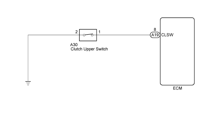
The clutch switch is mounted on the clutch pedal. The switch is turned off when depressing the clutch pedal, and transmits a signal to the ECM.
| DTC Detection Drive Pattern | DTC Detection Condition | Trouble Area |
|---|---|---|
| Gears are shifted more than 10 times | No clutch switch signals to ECM despite gears being shifted. (2 trip detection logic) |
|
WIRING DIAGRAM
INSPECTION PROCEDURE
Note
When replacing the ECM, the ECM needs Registration and Initialization Click here.
Tech Tips
When the ECM must be replaced, before replacing the ECM, perform the "Learning Values Save" function using the intelligent tester. Then after installing the new ECM, perform all of the initializations/registrations for the "Learning Values Write" function by following the instructions shown on the tester display.
PROCEDURE
-
INSPECT CLUTCH SWITCH ASSEMBLY
-
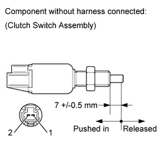
Remove the clutch switch assembly.
-
Measure the resistance according to the value(s) in the table below.
Standard Resistance Tester Connection Switch Condition Specified Condition 1 - 2 Pushed in Below 1 Ω Released 10 kΩ or higher -
Reinstall the clutch switch assembly.
NG 
REPLACE CLUTCH SWITCH ASSEMBLY Click here
OK 
-
-
CHECK CLUTCH SWITCH INSTALLATION
-
Check the clutch switch installation Click here.
OK Clutch switch is installed correctly.
NG
SECURELY REINSTALL CLUTCH SWITCH ASSEMBLY Click here
OK
-
-
CHECK HARNESS AND CONNECTOR (ECM - CLUTCH SWITCH - BODY GROUND)
-
Disconnect the clutch switch connector.
-
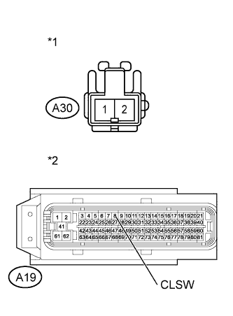
Text in Illustration *1 Front view of wire harness connector
(to Clutch Switch)
*2 Front view of wire harness connector
(to ECM)
Disconnect the ECM connector.
-
Measure the resistance according to the value(s) in the table below.
Standard Resistance (Check for Open) Tester Connection Condition Specified Condition A30-1 - A19-8 (CLSW) Always Below 1 Ω A30-2 - Body ground Always Below 1 Ω Standard Resistance (Check for Short) Tester Connection Condition Specified Condition A30-1 or A19-8 (CLSW) - Body ground Always 10 kΩ or higher -
Reconnect the clutch switch connector.
NG
REPAIR OR REPLACE HARNESS OR CONNECTOR Click here
OK
-
-
REPLACE ECM
-
Replace the ECM Click here.
NEXT
CONFIRM WHETHER MALFUNCTION HAS BEEN SUCCESSFULLY REPAIRED Click here
-
-
SECURELY REINSTALL CLUTCH SWITCH ASSEMBLY
-
Securely reinstall the clutch switch assembly Click here.
NEXT
CONFIRM WHETHER MALFUNCTION HAS BEEN SUCCESSFULLY REPAIRED Click here
-
-
REPLACE CLUTCH SWITCH ASSEMBLY
-
Replace the clutch switch assembly Click here.
NEXT
CONFIRM WHETHER MALFUNCTION HAS BEEN SUCCESSFULLY REPAIRED Click here
-
-
REPAIR OR REPLACE HARNESS OR CONNECTOR
NEXT
-
CONFIRM WHETHER MALFUNCTION HAS BEEN SUCCESSFULLY REPAIRED
-
Connect the intelligent tester to the DLC3.
-
Clear the DTCs Click here.
-
Start the engine.
-
Change the shift more than 10 times during city driving.
-
Confirm that the DTC is not output again.
NEXT 
END
-