ECD SYSTEM, Diagnostic DTC:P0201, P0202, P0203, P0204, P062D

| DTC Code | DTC Name |
|---|---|
| P0201 | Injector Circuit / Open - (Cylinder 1) |
| P0202 | Injector Circuit / Open - (Cylinder 2) |
| P0203 | Injector Circuit / Open - (Cylinder 3) |
| P0204 | Injector Circuit / Open - (Cylinder 4) |
| P062D | No. 1 Fuel Injector Driver Circuit Performance |
DESCRIPTION
The injectors are installed in the cylinder head and inject fuel into the cylinders based on the signals from the ECM.
Tech Tips
Injector driver is built in the ECM.
| DTC Detection Drive Pattern | DTC Detection Condition | Trouble Area |
|---|---|---|
| Engine idles for approximately 15 seconds | Open or short in injector circuit (cylinder No. 1) for 0.5 seconds or more (1 trip detection logic) |
|
| DTC Detection Drive Pattern | DTC Detection Condition | Trouble Area |
|---|---|---|
| Engine idles for approximately 15 seconds | Open or short in injector circuit (cylinder No. 2) for 0.5 seconds or more (1 trip detection logic) |
|
| DTC Detection Drive Pattern | DTC Detection Condition | Trouble Area |
|---|---|---|
| Engine idles for approximately 15 seconds | Open or short in injector circuit (cylinder No. 3) for 0.5 seconds or more (1 trip detection logic) |
|
| DTC Detection Drive Pattern | DTC Detection Condition | Trouble Area |
|---|---|---|
| Engine idles for approximately 15 seconds | Open or short in injector circuit (cylinder No. 4) for 0.5 seconds or more (1 trip detection logic) |
|
| DTC Detection Drive Pattern | DTC Detection Condition | Trouble Area |
|---|---|---|
| Engine idles for approximately 15 seconds | Either of following conditions is met:
(1 trip detection logic) |
|
Tech Tips
-
If DTC P0201, P0202, P0203, P0204 and/or P062D is stored, the following symptoms may appear:
-
Engine stall
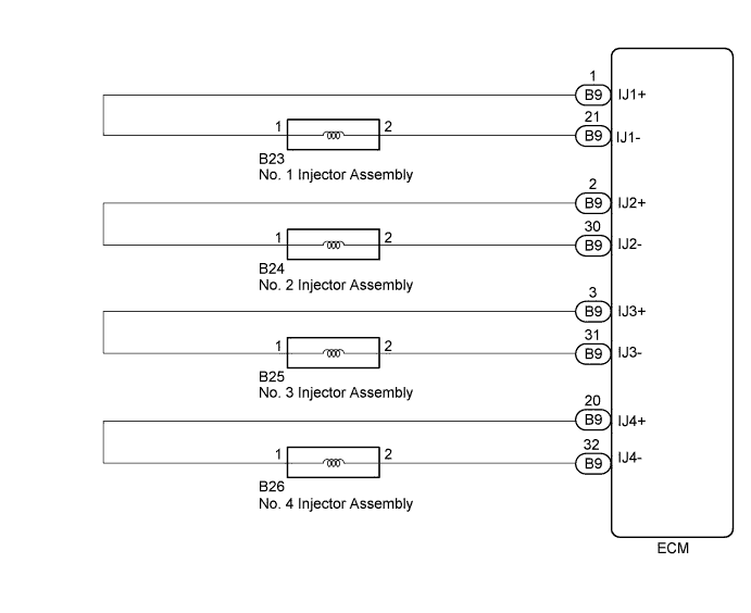
WIRING DIAGRAM
INSPECTION PROCEDURE
Note
Before proceeding to the diagnosis procedure, please carry out the below operations and check the cylinder.
1. Disconnect the injector connector of the cylinder number 2. Then turn the ignition switch to ON.
2. Check the DTC to see if P0202 is output.
3. If the output DTC is a different to P0202, follow the below instructions and carry out a diagnosis on the relevant cylinder.
Tech Tips
If the DTC is the same, conduct a diagnosis on that cylinder which the output DTC indicates.
| Result |
|---|
| If P0202 is output, repair cylinder number 3 |
| If P0203 is output, repair cylinder number 4 |
| If P0204 is output, repair cylinder number 2 |
Note
When replacing the ECM and/or fuel injector, the ECM needs Registration and Initialization Click here.
Tech Tips
-
When the ECM must be replaced, before replacing the ECM, perform the "Learning Values Save" function using the intelligent tester. Then after installing the new ECM, perform all of the initializations/registrations for the "Learning Values Write" function by following the instructions shown on the tester display.
-
Read freeze frame data using the intelligent tester. Freeze frame data records the engine condition when malfunctions are detected. When troubleshooting, freeze frame data can help determine if the vehicle was moving or stationary, if the engine was warmed up or not, and other data from the time the malfunction occurred.
PROCEDURE
-
INSPECT INJECTOR ASSEMBLY
-
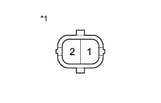
Text in Illustration *1 Component without harness connected
(Injector Assembly)
Disconnect the injector assembly connector.
-
Measure the resistance according to the value(s) in the table below.
Standard Resistance Tester Connection Condition Specified Condition 1 - 2 20°C 150 to 210 kΩ -
Reconnect the injector assembly connector.
NG 
REPLACE INJECTOR ASSEMBLY OF MALFUNCTIONING CYLINDER Click here
OK 
-
-
CHECK HARNESS AND CONNECTOR (INJECTOR ASSEMBLY - ECM)
-
Disconnect the injector assembly connector.
-
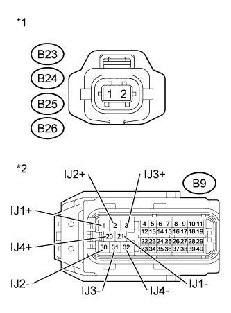
Text in Illustration *1 Front view of wire harness connector
(to Injector Assembly)
*2 Front view of wire harness connector
(to ECM)
Disconnect the ECM connector.
-
Measure the resistance according to the value(s) in the table below.
Standard Resistance (Check for Open) Tester Connection Condition Specified Condition B23-1 - B9-1 (IJ1+) Always Below 1 Ω B23-2 - B9-21 (IJ1-) Always Below 1 Ω B24-1 - B9-2 (IJ2+) Always Below 1 Ω B24-2 - B9-30 (IJ2-) Always Below 1 Ω B25-1 - B9-3 (IJ3+) Always Below 1 Ω B25-2 - B9-31 (IJ3-) Always Below 1 Ω B26-1 - B9-20 (IJ4+) Always Below 1 Ω B26-2 - B9-32 (IJ4-) Always Below 1 Ω Standard Resistance (Check for Short) Tester Connection Condition Specified Condition B23-1 or B9-1 (IJ1+) - Body ground Always 10 kΩ or higher B23-2 or B9-21 (IJ1-) - Body ground Always 10 kΩ or higher B24-1 or B9-2 (IJ2+) - Body ground Always 10 kΩ or higher B24-2 or B9-30 (IJ2-) - Body ground Always 10 kΩ or higher B25-1 or B9-3 (IJ3+) - Body ground Always 10 kΩ or higher B25-2 or B9-31 (IJ3-) - Body ground Always 10 kΩ or higher B26-1 or B9-20 (IJ4+) - Body ground Always 10 kΩ or higher B26-2 or B9-32 (IJ4-) - Body ground Always 10 kΩ or higher -
Reconnect the injector assembly connector.
-
Reconnect the ECM connector.
NG
REPAIR OR REPLACE HARNESS OR CONNECTOR Click here
OK
-
-
REPLACE ECM
-
Replace the ECM Click here.
NEXT
CONFIRM WHETHER MALFUNCTION HAS BEEN SUCCESSFULLY REPAIRED Click here
-
-
REPAIR OR REPLACE HARNESS OR CONNECTOR
NEXT
CONFIRM WHETHER MALFUNCTION HAS BEEN SUCCESSFULLY REPAIRED Click here
-
REPLACE INJECTOR ASSEMBLY OF MALFUNCTIONING CYLINDER
-
Replace the injector of malfunctioning cylinder Click here.
NEXT
-
-
PERFORM REGISTRATION AND INITIALIZATION
-
Register the injector compensation code Click here.
-
Perform Pilot Quantity Learning Values Reset Click here.
NEXT
-
-
BLEED AIR
-
Bleed air from fuel system Click here.
NEXT
-
-
CONFIRM WHETHER MALFUNCTION HAS BEEN SUCCESSFULLY REPAIRED
-
Connect the intelligent tester to the DLC3.
-
Clear the DTCs Click here.
-
Start the engine and turn the tester on.
-
Allow the engine to idle for 15 seconds or more.
-
Enter the following menus: Powertrain / Engine and ECT / DTC.
-
Confirm that the DTC is not output again.
NEXT 
END
-