ECD SYSTEM, Diagnostic DTC:P0130

| DTC Code | DTC Name |
|---|---|
| P0130 | Heated Oxygen (A/F) Sensor Circuit Malfunction (Bank 1 Sensor 1) |
DESCRIPTION
Refer to DTC P0131 Click here.
| DTC Detection Drive Pattern | DTC Detection Condition | Trouble Area |
|---|---|---|
| Vehicle driving with warm engine | One of the following conditions is met: (1 trip detection logic)
|
|
| All of the following conditions are met
|
The measured air fuel ratio is higher than high side calculated threshold or lower than low side calculated threshold |
|
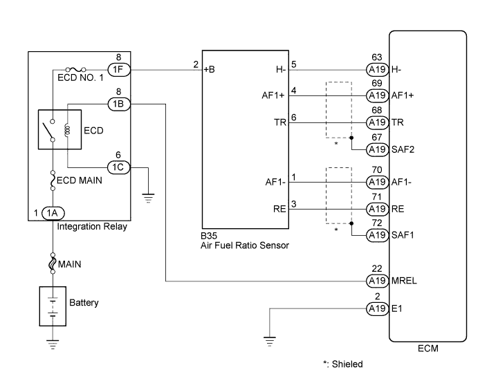
WIRING DIAGRAM
INSPECTION PROCEDURE
Note
-
When replacing the ECM and/or air fuel ratio sensor, the ECM needs Registration and Initialization Click here.
-
Inspect the fuses for circuits related to this system before performing the following inspection procedure.
Tech Tips
-
When the ECM must be replaced, before replacing the ECM, perform the "Learning Values Save" function using the intelligent tester. Then after installing the new ECM, perform all of the initializations/ registrations for the "Learning Values Write" function by following the instructions shown on the tester display.
-
Read freeze frame data using the intelligent tester. Freeze frame data records the engine condition when malfunctions are detected. When troubleshooting, freeze frame data can help determine if the vehicle was moving or stationary, if the engine was warmed up or not, and other data from the time the malfunction occurred.
PROCEDURE
-
CHECK ANY OTHER DTCS OUTPUT (IN ADDITION TO DTC P0130)
-
Connect the intelligent tester to the DLC3.
-
Turn the ignition switch to ON and turn the tester on.
-
Enter the following menus: Powertrain / Engine and ECT / DTC.
-
Read DTCs.
Result Result Proceed to P0130 A P0130 and other DTCs B Tech Tips
If any DTCs other than P0130 are output, troubleshoot those DTCs first.
B 
GO TO DTC CHART Click here
A 
-
-
INSPECT AIR FUEL RATIO SENSOR (HEATER RESISTANCE)
-
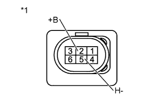
Text in Illustration *1 Component without harness connected
(Air Fuel Ratio Sensor)
Disconnect the air fuel ratio sensor connector.
-
Measure the resistance according to the value(s) in the table below.
Standard Resistance Tester Connection Condition Specified Condition 2 (+B) - 5 (H-) 20°C (68°F) 2.0 to 5.0 Ω -
Reconnect the air fuel ratio sensor connector.
NG 
REPLACE AIR FUEL RATIO SENSOR Click here
OK
-
-
CHECK HARNESS AND CONNECTOR (POWER SOURCE)
-
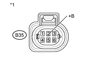
Text in Illustration *1 Front view of wire harness connector
(to Air Fuel Ratio Sensor)
Disconnect the air fuel ratio sensor connector.
-
Measure the voltage according to the value(s) in the table below.
Standard Voltage Tester Connection Switch Condition Specified Condition B35-2 (+B) - Body ground Ignition switch ON 11 to 14 V -
Reconnect the air fuel ratio sensor connector.
NG
CHECK HARNESS AND CONNECTOR (AIR FUEL RATIO SENSOR - INTEGRATION RELAY) Click here
OK
-
-
CHECK HARNESS AND CONNECTOR (AIR FUEL RATIO SENSOR - ECM)
-
Disconnect the air fuel ratio sensor connector.
-
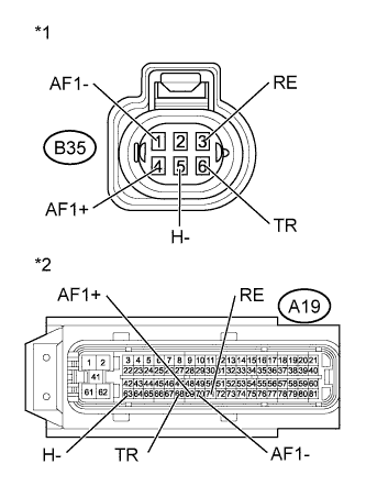
Text in Illustration *1 Front view of wire harness connector
(to Air Fuel Ratio Sensor)
*2 Front view of wire harness connector
(to ECM)
Disconnect the ECM connector.
-
Measure the resistance according to the value(s) in the table below.
Standard Resistance (Check for Open) Tester Connection Condition Specified Condition B35-4 (AF1+) - A19-69 (AF1+) Always Below 1 Ω B35-6 (TR) - A19-68 (TR) Always Below 1 Ω B35-1 (AF1-) - A19-70 (AF1-) Always Below 1 Ω B35-3 (RE) - A19-71 (RE) Always Below 1 Ω B35-5 (H-) - A19-63 (H-) Always Below 1 Ω Standard Resistance (Check for Short) Tester Connection Condition Specified Condition B35-4 (AF1+) or A19-69 (AF1+) - Body ground Always 10 kΩ or higher B35-6 (TR) or A19-68 (TR) - Body ground Always 10 kΩ or higher B35-1 (AF1-) or A19-70 (AF1-) - Body ground Always 10 kΩ or higher B35-3 (RE) or A19-71 (RE) - Body ground Always 10 kΩ or higher B35-5 (H-) or A19-63 (H- ) - Body ground Always 10 kΩ or higher -
Reconnect the air fuel ratio sensor connector.
-
Reconnect the ECM connector.
NG
REPAIR OR REPLACE HARNESS OR CONNECTOR Click here
OK
-
-
REPLACE AIR FUEL RATIO SENSOR
-
Replace the air fuel ratio sensor Click here.
-
Perform the A/F Sensor Compensation Reset Click here.
NEXT
-
-
CHECK WHETHER DTC OUTPUT RECURS (DTC P0130)
-
Connect the intelligent tester to the DLC3.
-
Clear the DTCs Click here.
-
Start the engine and warm it up until the engine coolant temperature reaches at 70°C (158°F) or more.
-
Drive the vehicle with a stop-and-go city drive pattern for more than 15 minutes.
-
Enter the following menus: Powertrain / Engine and ETC / DTC.
-
Read the DTCs.
Result Result Proceed to DTC P0130 A No DTC output B
B
END
A
-
-
REPLACE ECM
-
Replace the ECM Click here.
NEXT
CONFIRM WHETHER MALFUNCTION HAS BEEN SUCCESSFULLY REPAIRED Click here
-
-
CHECK HARNESS AND CONNECTOR (AIR FUEL RATIO SENSOR - INTEGRATION RELAY)
-
Disconnect the air fuel ratio sensor connector.
-
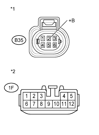
Text in Illustration *1 Front view of wire harness connector
(to Air Fuel Ratio Sensor)
*2 Front view of wire harness connector
(to Integration Relay)
Disconnect the integration relay connector.
-
Measure the resistance according to the value(s) in the table below.
Standard Resistance (Check for Open) Tester Connection Condition Specified Condition B35-2 (+B) - 1F-8 Always Below 1 Ω Standard Resistance (Check for Short) Tester Connection Condition Specified Condition B35-2 (+B) or 1F-8 - Body ground Always 10 kΩ or higher -
Reconnect the air fuel ratio sensor connector.
-
Reconnect the integration relay connector.
OK
CONFIRM WHETHER MALFUNCTION HAS BEEN SUCCESSFULLY REPAIRED Click here
NG
REPAIR OR REPLACE HARNESS OR CONNECTOR Click here
-
-
REPAIR OR REPLACE HARNESS OR CONNECTOR
NEXT
CONFIRM WHETHER MALFUNCTION HAS BEEN SUCCESSFULLY REPAIRED Click here
-
REPLACE AIR FUEL RATIO SENSOR
-
Replace the air fuel ratio sensor Click here.
-
Perform the A/F Sensor Compensation Reset Click here.
NEXT
-
-
CONFIRM WHETHER MALFUNCTION HAS BEEN SUCCESSFULLY REPAIRED
-
Connect the intelligent tester to the DLC3.
-
Clear the DTCs Click here.
-
Start the engine and warm it up until the engine coolant temperature reaches at 70°C (158°F) or more.
-
Drive the vehicle with a stop-and-go city drive pattern for more than 15 minutes.
-
Enter the following menus: Powertrain / Engine and ETC / DTC.
-
Confirm that the DTC is not output again.
NEXT 
END
-