ECD SYSTEM, Diagnostic DTC:P0087, P0088, P0191, P1229, P1272

| DTC Code | DTC Name |
|---|---|
| P0087 | Fuel Rail / System Pressure - Too Low |
| P0088 | Fuel Rail / System Pressure - Too High |
| P0191 | Fuel Rail Pressure Sensor Circuit Range / Performance |
| P1229 | Fuel Pump System |
| P1272 | Fuel Pressure Regulator System Malfunction |
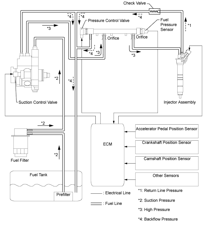
DESCRIPTION
With a cold engine, the internal pressure of the common rail is regulated by the pressure control valve. With a warm engine, it is regulated by the suction control valve. When the engine is running with light load, it is regulated by both the pressure control valve and the suction control valve of the supply pump.
Based on signals from the ECM, the pressure control valve opens when sudden deceleration occurs to prevent the fuel pressure from becoming too high.
These DTCs are to indicate in which mode a malfunction was detected. They do not indicate which part was malfunctioning when the fuel pressure malfunction was detected.
Tech Tips
All of the following DTCs can be detected when the engine speed is 630 rpm or more.
| DTC Detection Drive Pattern | DTC Detection Condition | Trouble Area |
|---|---|---|
| Following conditions is met: Idling with warm engine. Then fully depress and release the accelerator pedal repeatedly several times while keeping the vehicle stationary. Tech Tips Please refer to the Freeze Frame Data, in particular Vehicle Speed, Engine Speed, MAF, MAP, Calculate Load, Coolant Temp. |
Both of following conditions 1 and 2 are met (1 trip detection condition). 1. Transition period (within 1 second) during following fuel pressure control status. - Fuel pressure controlled with pressure control valve. - Fuel pressure controlled with suction control valve. - Fuel pressure controlled with both pressure control valve and suction control valve. 2. Common rail internal pressure is less than 12 to 15 MPa (varies with engine speed) for 0.3 seconds. |
|
| Control mode: Fuel pressure malfunction when in transition of control modes (within 1 second). |
||
| Purpose of Monitoring: Leakage in the high pressure range, injection nozzle stuck in open position, worn high pressure pump, worn injector, leaking pressure control valve. Possible errors in the low pressure stage: Pressure before gear pump too low, gear pump output too low (filter clogged up, leak on low pressure side), supply pump output too low. |
||
| DTC Detection Drive Pattern | DTC Detection Condition | Trouble Area |
|---|---|---|
| Following conditions is met: Idling with warm engine. Then fully depress and release the accelerator pedal repeatedly several times while keeping the vehicle stationary. Tech Tips Please refer to the Freeze Frame Data, in particular Vehicle Speed, Engine Speed, MAF, MAP, Calculate Load, Coolant Temp. |
Both of following conditions 1 and 2 are met (1 trip detection condition). 1. Transition period (within 1 second) during following fuel pressure control status. - Fuel pressure controlled with pressure control valve. - Fuel pressure controlled with suction control valve. - Fuel pressure controlled with both pressure control valve and suction control valve. 2. Common rail internal pressure is 175 MPa or more for 0.3 seconds. |
|
| Control mode: Fuel pressure malfunction when in transition of control modes (within 1 second). |
||
| Purpose of Monitoring: Pressure control valve stuck closed, pressure control valve supplied with power due to electrical error, suction control valve stuck in open position, orifice clogged up, suction control valve without power due to electrical error. Possible errors in the low pressure stage: Pressure before gear pump too great (e.g. supply pump with pressure control valve), pressure after orifice too high. |
||
| DTC Detection Drive Pattern | DTC Detection Condition | Trouble Area |
|---|---|---|
| Following conditions is met: Idling with warm engine. Then fully depress and release the accelerator pedal repeatedly several times while keeping the vehicle stationary. Tech Tips Please refer to the Freeze Frame Data, in particular Vehicle Speed, Engine Speed, MAF, MAP, Calculate Load, Coolant Temp. |
Both of following conditions 1 and 2 are met (1 trip detection condition). 1. Common rail internal pressure is regulated using both suction control valve (supply pump) and pressure control valve while engine running with light load (including idling) and fuel temperature above 15°C (59°F). 2. Common rail internal fuel pressure does not rise to target fuel pressure even when pressure control valve controlled to close fully. |
|
| Start the engine, then turn the ignition switch off and wait for 30 seconds or more when fuel temperature is 40°C (104°F) or more, and then turn the ignition switch to ON. Tech Tips Please refer to the Freeze Frame Data, in particular Vehicle Speed, Engine Speed, MAF, MAP, Calculate Load, Coolant Temp. |
After certain period of time has elapsed after engine stop (pressure control valve releases common rail internal pressure during this period), common rail internal pressure deviates from normal range. (Determination of a malfunction is conducted within a given time after the ignition switch is turned from ON to off. If a malfunction is detected within this time, the MIL is illuminated and a DTC is set when the ignition switch is next turned to ON.) (1 trip detection condition). |
|
| Control mode: Fuel pressure malfunction when in PCV and SCV cooperative control. |
||
| Purpose of Monitoring: Leakage in the high pressure range, injection nozzle stuck in open position, worn high pressure pump, worn injector, fuel pressure sensor malfunction, leaking pressure control valve. Possible errors in the low pressure stage. Pressure before gear pump too low, gear pump output too low (filter clogged up, leak on low pressure side), supply pump output too low. |
||
| DTC Detection Drive Pattern | DTC Detection Condition | Trouble Area |
|---|---|---|
| Drive the vehicle when fuel temperature is 15°C (59°F) or more. Tech Tips
|
Both of following conditions 1 and 2 are met (1 trip detection condition). 1. Common rail internal pressure is regulated using suction control valve (supply pump) while all of following conditions are met.* - Fuel temperature is above 15°C (59°F). - After certain period of time (maximum 300 seconds) has elapsed after engine start. - Medium or heavy load condition. Tech Tips *: At this time, suction control valve sending minimum volume of fuel depending on engine speed, load and fuel pressure, so it can reduce fuel temperature rising and reduce engine load. Fuel pressure control response with suction control valve is not as fast as pressure control valve. 2. One of the following conditions (a), (b) or (c) is met: (a) Common rail internal pressure is less than 12 to 15 MPa for 0.3 seconds. (b) Common rail internal pressure is 175 MPa or more for 0.3 seconds. (c) Actual fuel pressure remains lower than target rail pressure (The actual fuel pressure remains 17 to 20 MPa or lower for 1 second. Although the pressure control valve has sufficiently closed afterward, the actual fuel pressure still remains low for 1 second.) |
|
| Control mode: Fuel pressure malfunction when SCV (Suction Control Valve) control. |
||
| Purpose of Monitoring (DTC detection condition 2-(a)): Leakage in the high pressure range, injection nozzle stuck in open position, worn high pressure pump, worn injector, leaking pressure limiting or pressure control valve. Possible error in the low pressure stage. Pressure before gear pump too low, gear pump output too low (filter clogged up, leak on low pressure side), supply pump output too low. |
||
| Purpose of Monitoring (DTC detection condition 2-(b)): Suction control valve is stuck in open position, orifice clogged up, suction control valve without power due to electrical error. Possible error in the low pressure stage. Pressure before gear pump too great (e.g. in the case of an supply pump with pressure control valve), pressure after orifice too high. |
||
| Purpose of Monitoring (DTC detection condition 2-(c)): Leakage in the high pressure range, injection nozzle stuck in open position, worn high pressure pump, worn injector, leaking pressure limiting valve. Possible error in the low pressure stage. Pressure before gear pump too low, gear pump output too low (filter clogged up, leak on low pressure side), supply pump output too low. |
||
| DTC Detection Drive Pattern | DTC Detection Condition | Trouble Area |
|---|---|---|
| One of following conditions (a), (b), (c) or (d) is met: (a) When the fuel temperature is 15°C (59°F) or more and accelerator pedal fully released. (b) Engine idling (c) All driving condition when fuel temperature is 10°C (50°F) or less. (d) Within certain period of time (maximum 300 seconds) after engine start. Tech Tips Please refer to the Freeze Frame Data, in particular Vehicle Speed, Engine Speed, MAF, MAP, Calculate Load, Coolant Temp. |
Both of the following conditions 1 and 2 are met (1 trip detection logic). 1. Either of following conditions (1) or (2) is met (1) Common rail internal pressure is regulated using pressure control valve under one of the following condition is met* - Fuel temperature is below 15°C (59°F) - Within certain period of time after engine start (maximum 300 seconds, regardless of fuel temperature) (2) Common rail internal pressure is regulated using both suction control valve (supply pump) and pressure control valve while engine running with light load (including idling) and fuel temperature above 15°C (59°F) Tech Tips *: At this time, suction control valve sending maximum volume of fuel at that engine speed. Pressure control valve can reduce common rail pressure quickly during sudden deceleration. 2. One of the following conditions (a), (b), (c) or (d) is met: (a) Common rail internal pressure is less than 12 to 15 MPa for 0.3 seconds. (b) Common rail internal pressure is 175 MPa or more for 0.3 seconds. (c) Although the pressure control valve has sufficiently opened, actual fuel pressure remains higher than target fuel pressure by 25 MPa or more for 1 second. (d) Actual fuel pressure remains lower than target rail pressure (The actual fuel pressure remains 17 to 20 MPa or lower than target fuel pressure for 1 second. Although the pressure control valve has sufficiently closed afterward, the actual fuel pressure still remains low for 1 second.) |
|
| Control mode: Fuel pressure malfunction when in PCV (Pressure Control Valve) control, or when switching to PCV and SCV cooperative control. |
||
| Purpose of Monitoring (DTC detection condition 2-(a)): Leakage in the high pressure range, injection nozzle stuck in open position, worn high pressure pump, worn injector, leaking pressure limiting or pressure control valve. Possible error in the low pressure stage. Pressure before gear pump too low, gear pump output too low (filter clogged up, leak on low pressure side), supply pump output too low. |
||
| Purpose of Monitoring (DTC detection condition 2-(b)): Pressure control valve stuck closed, pressure control valve supplied with power due to electrical error, suction control valve stuck in open position, orifice clogged up, suction control valve without power due to electrical error. Possible error in the low pressure stage. Pressure before gear pump too great (e.g. in the case of an supply pump with pressure control valve), pressure after orifice too high. |
||
| Purpose of Monitoring (DTC detection condition 2-(c)): Leakage in the high pressure range, injection nozzle stuck in open position, worn high pressure pump, worn injector, leaking pressure limiting or pressure control valve. Possible error in the low pressure stage. Pressure before gear pump too low, gear pump output too low (filter clogged up, leak on low pressure side), supply pump output too low. |
||
| Purpose of Monitoring (DTC detection condition 2-(d)): Pressure control valve stuck, pressure control valve supplied with power due to electrical error. Possible error in the low pressure stage. Pressure control valve reflux too high. |
||
| DTC No. | Data List |
|---|---|
| P0087 P0088 P0191 P1229 P1272 |
|
Tech Tips
When the engine is running, the actual common rail internal pressure (Fuel Press) follows the target common rail internal pressure (Target Common Rail Pressure). Under a stable condition such as idling, Fuel Press is within +/-10000 kPa of Target Common Rail Pressure.
Tech Tips
-
If DTC P0087, P0088, P0191, P1229 or P1272 is stored, the following symptoms may appear.
-
Lack of power or engine stall due to fail-safe operation
-
If the Fuel Press is 175000 kPa or more.
-
Combustion noise worsens
-
If the Fuel Press is 15000 kPa or less.
-
Difficult to start
-
If the Fuel Press is more than "Target Common Rail Pressure + 20000 kPa".
-
Combustion noise worsens
-
If the Fuel Press is less than "Target Common Rail Pressure - 20000 kPa".
-
Difficult to start
-
Poor acceleration
-
Engine stall
INSPECTION PROCEDURE
Note
-
When replacing the ECM and/or fuel injector, the ECM needs Registration and Initialization Click here.
-
Inspect the fuses for circuits related to this system before performing the following inspection procedure.
Tech Tips
-
When the ECM must be replaced, before replacing the ECM, perform the "Learning Values Save" function using the intelligent tester. Then after installing the new ECM, perform all of the initializations/registrations for the "Learning Values Write" function by following the instructions shown on the tester display.
-
Read freeze frame data using the intelligent tester. Freeze frame data records the engine condition when malfunctions are detected. When troubleshooting, freeze frame data can help determine if the vehicle was moving or stationary, if the engine was warmed up or not, and other data from the time the malfunction occurred.
-
If the value of "Target Pump SCV Current" in the freeze frame data exceeds 1530 mA, the supply pump assembly may have a malfunction.
-
Before starting the inspection procedure, check the following items of freeze frame data carefully for identifying the cause of the malfunction, and in judging whether it was temporary or not.
-
Target Common Rail Pressure
-
Fuel Press
-
Target Pump SCV Current
-
Fuel Temperature
-
Engine Speed
-
MAF
-
MAP
-
Vehicle Speed
-
Coolant Temp.
PROCEDURE
-
CHECK ANY OTHER DTCS OUTPUT (IN ADDITION TO DTC P0087, P0088, P0191, P1229 OR P1272)
-
Connect the intelligent tester to the DLC3.
-
Turn the ignition switch to ON and turn the tester on.
-
Enter the following menus: Powertrain / Engine and ECT / DTC.
-
Record the stored DTCs and Freeze Frame Data.
Result Result Proceed to DTC P0087, P0088, P0191, P1229 or P1272 A DTC P0087, P0088, P0191, P1229 or P1272 and other DTCs B Tech Tips
If any DTCs other than P0087, P0088, P0191, P1229 or P1272 are output, troubleshoot those DTCs first.
B 
GO TO DTC CHART Click here
A 
-
-
CHECK FUEL RECEIVER GAUGE (AMOUNT OF FUEL)
-
Check if the fuel level is low.
Result Result Proceed to The fuel gauge (segment) blinks A The fuel gauge (segment) does not blink B
B 
CLEAR DTC Click here
A
-
-
ADD FUEL
NEXT
-
BLEED AIR FROM FUEL SYSTEM
-
Bleed air from fuel system Click here.
NEXT
-
-
CHECK WHETHER DTC OUTPUT RECURS (DTC P0087, P0088, P0191, P1229 OR P1272)
-
Connect the intelligent tester to the DLC3.
-
Clear the DTCs Click here.
-
Turn the ignition switch off and wait for 30 seconds.
-
If the DTC P1272 is stored in the result of Step 1, perform the (A) to (C) confirmation driving pattern process. If the result of Step 1 is other than DTC P1272, perform the (D) to (F) confirmation driving pattern process.
-
Start the engine when the fuel temperature is 15°C (59°F) or less. (A)
-
Drive the vehicle in 2nd gear. (B)
-
Fully depress the accelerator pedal, and then fully release it from engine speed of 3000 rpm or more. (C)
-
Allow the engine to idle until the engine coolant temperature reaches 75°C (167°F) or more. (D)
-
Drive the vehicle in 2nd gear. (E)
-
Fully depress the accelerator pedal, and then fully release it from engine speed of 3000 rpm or more. (F)
-
Enter the following menus: Powertrain / Engine and ECT / DTC.
-
Read the DTCs.
Tech Tips
Take a snapshot under a stable condition such as idling, confirm the Fuel Press is within +/-10000 kPa of Target Common Rail Pressure.
Tech Tips
Perform the following procedure using the tester to determine whether or not the DTC judgment has been carried out.
-
Enter the following menus: Powertrain / Engine and ECT / Utility / All Readiness.
-
Input DTC P0087, P0088, P0191, P1229 or P1272.
-
Check that STATUS is NORMAL. If STATUS is INCOMPLETE or UNKNOWN, repeat the confirmation driving pattern process.
Result Result Proceed to NORMAL A ABNORMAL B
-
B
CLEAR DTC Click here
A 
DTC CAUSED BY RUNNING OUT OF FUEL
-
-
CLEAR DTC
-
Connect the intelligent tester to the DLC3.
-
Clear the DTCs Click here.
NEXT
-
-
CHECK ENGINE STARTING CONDITION
OK The engine can be started within 4 seconds. Note
Just after starting the engine, visually check for fuel leaks from the supply pump, the fuel injectors, the common rail, and the fuel pipes in high-pressure areas.
OK
CHECK FREEZE FRAME DATA (TARGET PUMP SCV CURRENT) Click here
NG
BLEED AIR FROM FUEL SYSTEM Click here
-
BLEED AIR FROM FUEL SYSTEM
-
Bleed air from fuel system Click here.
NEXT
-
-
CHECK ENGINE STARTING CONDITION
-
Check whether the engine can be started.
OK The engine can be started.
OK
CHECK FREEZE FRAME DATA (TARGET PUMP SCV CURRENT) Click here
NG
CHECK AND REPLACE FUEL INLET LINE Click here
-
-
CHECK AND REPLACE FUEL INLET LINE
-
Check the following items (fuel line from fuel tank to supply pump), and repair or replace the malfunctioning part if necessary.
-
Check for fuel filter clogging.
-
Check for fuel freezing in the fuel line when the cold condition.
-
Check for clogging or leaks in the fuel pipe and hose between the fuel tank and fuel supply pump.
-
NEXT
-
-
CHECK ENGINE STARTING CONDITION
-
Check whether the engine can be started.
OK The engine can be started.
OK
CHECK FREEZE FRAME DATA (TARGET PUMP SCV CURRENT) Click here
NG
REPLACE SUPPLY PUMP ASSEMBLY (SUCTION CONTROL VALVE) Click here
-
-
REPLACE SUPPLY PUMP ASSEMBLY (SUCTION CONTROL VALVE)
-
Replace the fuel supply pump assembly Click here.
NEXT
-
-
BLEED AIR FROM FUEL SYSTEM
-
Bleed air from fuel system Click here.
NEXT
-
-
CHECK ENGINE STARTING CONDITION
-
Check whether the engine can be started.
OK The engine can be started.
OK
CHECK FREEZE FRAME DATA (TARGET PUMP SCV CURRENT) Click here
NG
REPLACE COMMON RAIL ASSEMBLY (PRESSURE CONTROL VALVE) Click here
-
-
REPLACE COMMON RAIL ASSEMBLY (PRESSURE CONTROL VALVE)
-
Replace the common rail assembly Click here.
NEXT
-
-
BLEED AIR FROM FUEL SYSTEM
-
Bleed air from fuel system Click here.
NEXT
-
-
CHECK FREEZE FRAME DATA (TARGET PUMP SCV CURRENT)
-
Read the value of Target Pump SCV Current in Freeze Frame Data recorded in Step 1.
Standard Tester Display
(Freeze Frame Data Item)
Specified Condition Target Pump SCV Current Below 1530 mA
NG
CHECK HARNESS AND CONNECTOR (SUCTION CONTROL VALVE - ECM) Click here
OK
-
-
CHECK FREEZE FRAME DATA (FUEL PRESS)
-
Read the value of Fuel Press and Target Common Rail Pressure in Freeze Frame Data recorded in Step 1.
Standard Tester Display
(Freeze Frame Data Item)
Specified Condition Fuel Press Below 175000 kPa -
Start the engine and warm it up.
-
Enter the following menus: Powertrain / Engine and ECT / Data List / Fuel Press and Target Common Rail Pressure.
-
Check that the Fuel Press is within the specification below.
Standard Fuel Press is within +/-10000 kPa of Target Common Rail Pressure when engine is idling. Result Result Proceed to Both conditions are met:
-
Fuel Press of Freeze Frame Data is 175000 kPa or more
-
Fuel Press is within +/-10000 kPa of Target Common Rail Pressure when engine is idling
B Except above A -
B
REPLACE COMMON RAIL ASSEMBLY Click here
A
-
-
CHECK FREEZE FRAME DATA (INJECTION FEEDBACK VAL #1 TO #4)
Tech Tips
Perform the procedures below to identify the malfunctioning cylinder.
-
Start the engine and warm it up until the engine coolant temperature reaches 75°C (167°F) or more.
-
Allow the engine to idle for 30 seconds or more.
-
Connect the intelligent tester to the DLC3.
-
Enter the following menus: Powertrain / Engine and ECT / Data List / Injection Feedback Val #1 to #4.
-
Read the value.
Standard Tester Display
(Data List Item)
Engine Condition Specified Condition Injection Feedback Val #1
Injection Feedback Val #2
Injection Feedback Val #3
Injection Feedback Val #4
Idling Between -2.0 mm3/st and 2.0 mm3/st
NG
PERFORM ACTIVE TEST USING INTELLIGENT TESTER (FUEL CUT FOR IDENTIFYING MALFUNCTION) Click here
OK
-
-
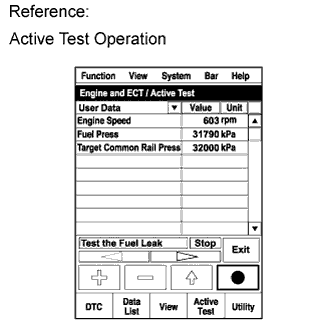
PERFORM ACTIVE TEST USING INTELLIGENT TESTER (TEST THE FUEL LEAK)
-
Connect the intelligent tester to the DLC3.
-
Turn the ignition switch to ON and turn the tester on.
-
Enter the following menus: Powertrain / Engine and ECT/ Active Test / Test the Fuel Leak / Data List / Fuel Press, Target Common Rail Pressure and Target Pump SCV Current.
-
Check the Fuel Press is within +/-10000 kPa of Target Common Rail Pressure when engine is idling and running at 3000 rpm without load.
-
Take a snapshot with the intelligent tester during the Active Test.
Tech Tips
Detailed graphs can be displayed by transferring the stored snapshot data from the tester to a PC (personal computer) with Intelligent Viewer installed.
-
Maintain the engine speed of 3500 rpm, and then press the "Start" button.
-
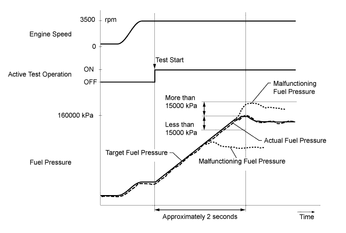
Measure the difference between the target fuel pressure (Target Common Rail Pressure) and the actual fuel pressure (Fuel Press) when the Active Test /Test the Fuel Leak is performed.
Note
The EPS, ABS and SRS warning lights may blink when the engine speed exceeds 3500 rpm during the operating this test.
Tech Tips
To ensure accurate measurements, perform the Active Test with measurements 5 times or more.
Standard The difference between the target fuel pressure and the actual fuel pressure is less than 15000 kPa when the target fuel pressure reaches the maximum value approximately 2 seconds after the Active Test starts. -
Read the value of Target Pump SCV Current in Data List when the Active Test / Test the Fuel Leak is performed.
Standard current Target Pump SCV Current is less than 1530 mA. Tech Tips
If the value of Target Pump SCV Current stored in Freeze Frame Data is higher than standard, intermittent sticking of the suction control valve may be the cause of the malfunction.
Result Result Proceed to Both results are within standard A Difference between target fuel pressure and actual fuel pressure is 15000 kPa or more B Target Pump SCV Current value is out of standard range C Both conditions are met:
-
Fuel Press is 175000 kPa or more during active test at 3500 rpm
-
Fuel Press is within +/-10000 kPa of Target Common Rail Pressure when engine is idling
D -
A
CONFIRM WHETHER MALFUNCTION HAS BEEN SUCCESSFULLY REPAIRED Click here
B
REPLACE SUPPLY PUMP ASSEMBLY Click here
C
CHECK HARNESS AND CONNECTOR (SUCTION CONTROL VALVE - ECM) Click here
D
REPLACE COMMON RAIL ASSEMBLY Click here
-
-
PERFORM ACTIVE TEST USING INTELLIGENT TESTER (FUEL CUT FOR IDENTIFYING MALFUNCTION)
-
Start the engine and warm it up until the engine coolant temperature reaches 75°C (167°F) or more.
-
Connect the intelligent tester to the DLC3.
-
Turn the tester on.
-
Enter the following menus: Powertrain / Engine and ECT / Active Test / Control the Cylinder#1 to #4 Fuel Cut.
-
Check the four cylinders in sequence to identify a faulty cylinder.
Tech Tips
-
DTCs may be output after this Active Test. Make sure to check for DTCs after this Active Test. If any DTCs are output, make sure to clear them Click here.
-
If the engine idling remains normal despite cutting off the fuel injection, the cylinder is malfunctioning.
-
NEXT
-
-
REPLACE INJECTOR ASSEMBLY (INJECTOR OF MALFUNCTIONING CYLINDER)
-
Replace the injector assembly of the malfunctioning cylinder Click here.
NEXT
-
-
PERFORM REGISTRATION AND INITIALIZATION
-
Perform registration of the fuel injector compensation code Click here.
NEXT
-
-
BLEED AIR FROM FUEL SYSTEM
-
Bleed air from fuel system Click here.
NEXT
CONFIRM WHETHER MALFUNCTION HAS BEEN SUCCESSFULLY REPAIRED Click here
-
-
REPLACE SUPPLY PUMP ASSEMBLY
Tech Tips
If the supply pump assembly has already been replaced in step 12, proceed to next step.
-
Replace the supply pump assembly Click here.
NEXT
-
-
BLEED AIR FROM FUEL SYSTEM
-
Bleed air from fuel system Click here.
NEXT
-
-
PERFORM ACTIVE TEST USING INTELLIGENT TESTER (TEST THE FUEL LEAK)
-
Connect the intelligent tester to the DLC3.
-
Turn the ignition switch to ON and turn the tester on.
-
Enter the following menus: Powertrain / Engine and ECT/ Active Test / Test the Fuel Leak / Data List / Fuel Press and Target Common Rail Pressure.
-
Take a snapshot with the intelligent tester during the Active Test.
Tech Tips
Detailed graphs can be displayed by transferring the stored snapshot data from the tester to a PC (personal computer) with Intelligent Viewer installed.
-
Maintain the engine speed of 3500 rpm, and then press the "Start" button.
-
Measure the difference between the target fuel pressure (Target Common Rail Pressure) and the actual fuel pressure (Fuel Press) when the Active Test /Test the Fuel Leak is performed.
Note
The EPS, ABS and SRS warning lights may blink when the engine speed exceeds 3500 rpm during the operating this test.
Tech Tips
To ensure accurate measurements, perform the Active Test with measurements 5 times or more.
Standard The difference between the target fuel pressure and the actual fuel pressure is less than 15000 kPa when the target fuel pressure reaches the maximum value approximately 2 seconds after the Active Test starts. Result Result Proceed to Difference between target fuel pressure and actual fuel pressure is 15000 kPa or more A Difference between target fuel pressure and actual fuel pressure is less than 15000 kPa B
B
CONFIRM WHETHER MALFUNCTION HAS BEEN SUCCESSFULLY REPAIRED Click here
A
-
-
REPLACE COMMON RAIL ASSEMBLY
Tech Tips
If the common rail assembly has already been replaced in step 15, proceed to next step.
-
Replace the common rail assembly Click here.
NEXT
-
-
BLEED AIR FROM FUEL SYSTEM
-
Bleed air from fuel system Click here.
NEXT
CONFIRM WHETHER MALFUNCTION HAS BEEN SUCCESSFULLY REPAIRED Click here
-
-
CHECK HARNESS AND CONNECTOR (SUCTION CONTROL VALVE - ECM)
-
Disconnect the suction control valve connector.
-
Disconnect the ECM connector.
-
Measure the resistance according to the value(s) in the table below.
Standard Resistance (Check for Open) Tester Connection Condition Specified Condition B42-2 - B9-12 (PCV) Always Below 1 Ω Standard Resistance (Check for Short) Tester Connection Condition Specified Condition B42-2 or B9-12 (PCV) - Body ground Always 10 kΩ or higher -
Reconnect the suction control valve connector.
-
Reconnect the ECM connector.
NG
REPAIR OR REPLACE HARNESS OR CONNECTOR Click here
OK
-
-
REPLACE SUPPLY PUMP ASSEMBLY
Tech Tips
If the supply pump assembly has already been replaced in step 12, proceed to next step.
-
Replace the supply pump assembly Click here.
NEXT
-
-
BLEED AIR FROM FUEL SYSTEM
-
Bleed air from fuel system Click here.
NEXT
CONFIRM WHETHER MALFUNCTION HAS BEEN SUCCESSFULLY REPAIRED Click here
-
-
REPAIR OR REPLACE HARNESS OR CONNECTOR
NEXT
-
CONFIRM WHETHER MALFUNCTION HAS BEEN SUCCESSFULLY REPAIRED
-
Connect the intelligent tester to the DLC3.
-
Clear the DTCs Click here.
-
Turn the ignition switch off and wait for 30 seconds.
-
If the DTC P1272 is stored in the result of Step 1, perform the (A) to (C) confirmation driving pattern process. If the result of Step 1 is other than DTC P1272, perform the (D) to (F) confirmation driving pattern process.
-
Start the engine when the fuel temperature is 15°C (59°F) or less. (A)
-
Drive the vehicle in 2nd gear. (B)
-
Fully depress the accelerator pedal, and then fully release it from engine speed of 3000 rpm or more. (C)
-
Allow the engine to idle until the engine coolant temperature reaches 75°C (167°F) or more. (D)
-
Drive the vehicle in 2nd gear. (E)
-
Fully depress the accelerator pedal, and then fully release it from engine speed of 3000 rpm or more. (F)
-
Enter the following menus: Powertrain / Engine and ECT / DTC.
-
Confirm that the DTC is not output again.
Tech Tips
Perform the following procedure using the tester to determine whether or not the DTC judgment has been carried out.
-
Enter the following menus: Powertrain / Engine and ECT / Utility / All Readiness.
-
Input DTC P0087, P0088, P0191, P1229 or P1272.
-
Check that STATUS is NORMAL. If STATUS is INCOMPLETE or UNKNOWN, repeat the confirmation driving pattern process.
-
NEXT
END
-