ECD SYSTEM PRECAUTION

-
INITIALIZATION AND REGISTRATION
Note
When the ECM and/or the other component(s), mentioned below are replaced, perform the following utility items, referring to the corresponding Initialization and Registration procedure.
Tech Tips
When the ECM and other component(s) are replaced at the same time, perform the following utility items by following the instructions shown on the tester display, starting with the ECM.
Replacement Part Utility Item See page ECM
-
Learning Values Save
-
Learning Values Write
Injector Assembly
-
Injector Compensation
-
Pilot Quantity Learning Values Reset
DPF Catalyst DPF Deterioration Record Clear* A/F Sensor A/F Sensor Compensation Reset Engine Assembly
-
Injector Compensation
-
Pilot Quantity Learning Values Reset
-
*: "DPF Deterioration Record Clear" appears on the intelligent tester display only for vehicles with the DPF system.
DPF Deterioration Record means the ash accumulation volume in the DPF catalytic converter calculated by the ECM. If the ash accumulation volume in the DPF catalytic converter increases, the difference in pressure in front of and behind the DPF catalytic converter will increase. The difference in pressure in front of and behind the DPF catalytic converter is offset depending on the volume of accumulated ash.
Tech Tips
-
When the ECM must be replaced, before replacing the ECM, perform the "Learning Values Save" function using the intelligent tester. Then after installing the new ECM, perform all of the initializations/registrations for the "Learning Values Write" function by following the instructions shown on the tester display.
-
After replacing fuel injector(s), perform both the "Injector Compensation" and the "Pilot Quantity Learning Values Reset" functions using the intelligent tester.
-
After replacing the engine assembly, perform both the "Injector Compensation" and the "Pilot Quantity Learning Values Reset" functions using the intelligent tester.
-
-
INJECTOR COMPENSATION CODE
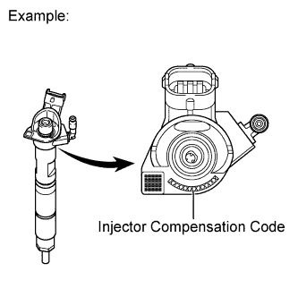
Tech Tips
Each fuel injector has different fuel injection characteristics. In order to optimize the fuel injections, the ECM uses the compensation codes to balance the different fuel injections between each injector. Injector compensation codes are 12-digit, alphanumeric values printed on the head of each injector.
Note
If an incorrect fuel injector compensation code is input into the ECM, the engine assembly may rattle or engine idling may become rough. In addition, engine failure may occur and the life of the engine may be shortened.
-
OIL MAINTENANCE LIGHT AND MIL
Tech Tips
The troubleshooting procedure will be different depending on the combination of the output DTCs and indicator light status (oil maintenance light and MIL) in the combination meter. Thus, perform troubleshooting referring to the table below.
-
Connect the intelligent tester to the DLC3.
-
Turn the ignition switch to ON and turn the tester on.
-
Enter the following menus: Powertrain / Engine and ECT / DTC.
-
Read the output DTCs combination of P250D, P252F and P2463.
No. Oil Maintenance Light Status MIL Status Note Proceed to 0 OFF OFF Normal condition - 1 Blinks OFF
-
(a) Travel distance oil change request
-
(b) Cumulative soot oil change request
-
(c) Oil high level malfunction detected in 2 consecutive trips*1
-
Replace engine oil and filter
-
Reset oil maintenance light
-
Drive vehicle to reset oil high level malfunction
2 ON OFF Oil maintenance light ON when vehicle driven without replacing engine oil after either of the above conditions 1-(a) or 1-(b) is detected 3
*1
ON OFF
DTC P252F detected
DTC P252F is detected when 400 km (249 miles) traveled after the above condition 1-(c) is detected P252F
4
*1
ON ON
DTC P250D and P252F detected
-
DTC P250D is detected when oil level sensor circuit opens
-
DTC P252F is detected when 400 km (249 miles) traveled after P250D detected
P250D
5
*1
ON ON
DTC P252F and P2463 detected
-
DTC P252F is detected when 400 km (249 miles) traveled after the above condition 1-(c) is detected
-
DTC P2463 is detected when 1000 km*2 (621 miles) traveled after P252F detected
P2463
6
*1
ON ON
DTC P250D, P252F and P2463 detected
-
DTC P250D is detected when oil level sensor circuit opens
-
DTC P252F is detected when 400 km (249 miles) traveled after P250D detected
-
DTC P2463 is detected when 1000 km*2 (621 miles) traveled after P252F detected
P250D
P2463
-
*1: w/ DPF System only
Tech Tips
*2: DTC P2463 detection distance varies depending on the operation conditions.
-
-
-
FOR USING INTELLIGENT TESTER
CAUTION:
-
Read the instruction manuals before using the tester.
-
Prevent the tester cable from being caught on the pedals, shift lever and steering wheel when driving with the tester connected to the vehicle.
-
When driving the vehicle for testing purposes and using the tester, two persons are required. One for driving the vehicle, and the other for operating the tester.
-
-
IGNITION SWITCH EXPRESSIONS
-
The type of ignition switch used on this model differs according to the specifications of the vehicle. The expressions listed in the table below are used in this section.
Expression Ignition Switch (Position) Engine Switch (Condition) Ignition switch off LOCK Off Ignition switch ACC ACC On (ACC) Ignition switch ON ON On (IG) Engine start START Start
-