ECD SYSTEM, Diagnostic DTC:P0045, P0047, P0048

| DTC Code | DTC Name |
|---|---|
| P0045 | Turbocharger / Supercharger Boost Control Solenoid Circuit / Open |
| P0047 | Turbocharger/Supercharger Boost Control "A" Circuit Low |
| P0048 | Turbocharger/Supercharger Boost Control "A" Circuit High |
DESCRIPTION
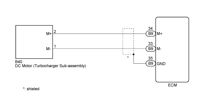
These DTCs indicates that the DC motor of the turbocharger is malfunctioning. The ECM monitors the DC motor current to detect an open or short in the DC motor circuit. If the current meets the criteria, the ECM stores a DTC and illuminates the MIL immediately.
The DC motor is used to operate the nozzle vane of the turbocharger. The nozzle vane opens and closes to change the velocity of exhaust emissions in order to control the turbo pressure. The ECM varies the duty-cycle of the DC motor in accordance with the driving condition.
If the nozzle vane is stuck closed (DC motor stuck off), the drivability may deteriorate at wide open throttle. If the nozzle vane is stuck open (DC motor stuck on), the drivability may deteriorate at intermediate throttle or the engine power may be in sufficient.
| DTC Detection Drive Pattern | DTC Detection Condition | Trouble Area |
|---|---|---|
| Turn the ignition switch to ON and wait for 10 seconds (Monitor this DTC only once per driving cycle) |
Open in DC motor (turbocharger sub-assembly) circuit (1 trip detection logic) |
|
| DTC Detection Drive Pattern | DTC Detection Condition | Trouble Area |
|---|---|---|
| Engine idling for 30 seconds | Short in DC motor (turbocharger sub-assembly) circuit (1 trip detection logic) |
|
| DTC Detection Drive Pattern | DTC Detection Condition | Trouble Area |
|---|---|---|
| Engine idling for 30 seconds | Short in DC motor (turbocharger sub-assembly) circuit (1 trip detection logic) |
|
Tech Tips
-
If DTC P0045, P0047 and/or P0048 is stored, the following symptoms may appear.
-
Poor acceleration
WIRING DIAGRAM
INSPECTION PROCEDURE
Note
When replacing the ECM, the ECM needs Registration and Initialization Click here.
Tech Tips
-
When the ECM must be replaced, before replacing the ECM, perform the "Learning Values Save" function using the intelligent tester. Then after installing the new ECM, perform all of the initializations/registrations for the "Learning Values Write" function by following the instructions shown on the tester display.
-
Read freeze frame data using the intelligent tester. Freeze frame data records the engine condition when malfunctions are detected. When troubleshooting, freeze frame data can help determine if the vehicle was moving or stationary, if the engine was warmed up or not, and other data from the time the malfunction occurred.
PROCEDURE
-
INSPECT TURBOCHARGER SUB-ASSEMBLY (DC MOTOR)
-
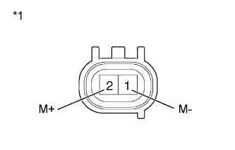
Text in Illustration *1 Component without harness connected
(DC Motor)
Disconnect the DC motor connector.
-
Measure the resistance according to the value(s) in the table below.
Standard Resistance Tester Connection Condition Specified Condition 1 (M-) - 2 (M+) Always 0.3 to 100 Ω -
Reconnect the DC motor connector.
NG 
REPLACE TURBOCHARGER SUB-ASSEMBLY Click here
OK 
-
-
CHECK HARNESS AND CONNECTOR (DC MOTOR - ECM)
-
Disconnect the DC motor connector.
-
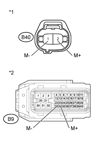
Text in Illustration *1 Front view of wire harness connector
(to DC Motor)
*2 Front view of wire harness connector
(to ECM)
Disconnect the ECM connector.
-
Measure the resistance according to the value(s) in the table below.
Standard Resistance (Check for Open) Tester Connection Condition Specified Condition B40-2 (M+) - B9-34 (M+) Always Below 1 Ω B40-1 (M-) - B9-33 (M-) Always Below 1 Ω Standard Resistance (Check for Short) Tester Connection Condition Specified Condition B40-2 (M+) or B9-34 (M+) - Body ground Always 10 kΩ or higher B40-1 (M-) or B9-33 (M-) - Body ground Always 10 kΩ or higher -
Reconnect the DC motor connector.
-
Reconnect the ECM connector.
NG
REPAIR OR REPLACE HARNESS OR CONNECTOR Click here
OK
-
-
REPLACE ECM
-
Replace the ECM Click here.
NEXT
CONFIRM WHETHER MALFUNCTION HAS BEEN SUCCESSFULLY REPAIRED Click here
-
-
REPLACE TURBOCHARGER SUB-ASSEMBLY
-
Replace the turbocharger sub-assembly Click here.
NEXT
CONFIRM WHETHER MALFUNCTION HAS BEEN SUCCESSFULLY REPAIRED Click here
-
-
REPAIR OR REPLACE HARNESS OR CONNECTOR
NEXT
-
CONFIRM WHETHER MALFUNCTION HAS BEEN SUCCESSFULLY REPAIRED
-
Connect the intelligent tester to the DLC3.
-
Clear the DTCs Click here.
-
Turn the ignition switch off.
-
Turn the ignition switch to ON.
-
Turn the ignition switch off and wait for 30 seconds or more.
-
Turn the ignition switch to ON and wait for 10 seconds or more.
-
Start the engine.
-
Allow the engine to idle for 30 seconds or more.
-
Enter the following menus: Powertrain / Engine and ECT / DTC.
-
Confirm that the DTC is not output again.
NEXT 
END
-