SFI SYSTEM Starter Signal Circuit
DESCRIPTION
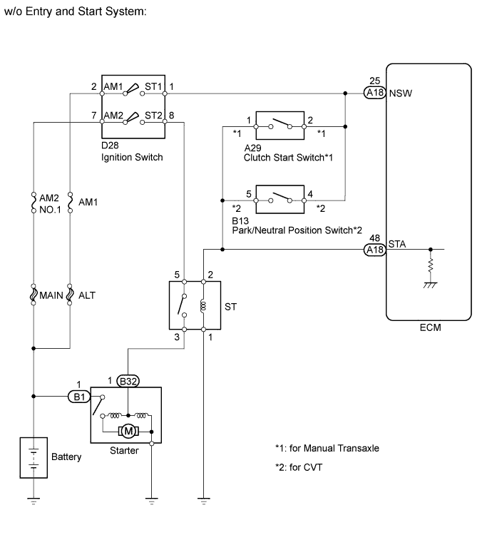
While the engine is being cranked, current flows from terminal ST1 of the ignition switch to the clutch start switch or the park/neutral position switch and also flows to terminal STA of the ECM (STA Signal).
WIRING DIAGRAM
INSPECTION PROCEDURE
PROCEDURE
-
READ VALUE USING INTELLIGENT TESTER (STARTER SIGNAL)
-
Connect an intelligent tester to the DLC3.
-
Turn the ignition switch to ON.
-
Turn the tester on.
-
Enter the following menus: Powertrain / Engine and ECT / Data List / Starter Signal.
-
Check the result when the ignition switch is turned ON and the engine starts.
OK Condition Starter Signal Ignition switch ON OFF Engine start ON Result Result Proceed to Outside standard range (for manual transaxle) A Outside standard range (for CVT) B Within standard range (for manual transaxle) C Within standard range (for CVT) D
B 
INSPECT PARK/NEUTRAL POSITION SWITCH ASSEMBLY Click here
C
CHECK HARNESS AND CONNECTOR (CLUTCH START SWITCH ASSEMBLY- ECM - ST RELAY) Click here
D
CHECK HARNESS AND CONNECTOR (PARK/NEUTRAL POSITION SWITCH ASSEMBLY - ECM - ST RELAY) Click here
A 
-
-
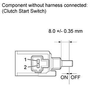
INSPECT CLUTCH SWITCH START ASSEMBLY
-
Disconnect the clutch start switch assembly connector.
-
Measure the resistance according to the value(s) in the table below.
Standard Resistance Tester Connection Switch Condition Specified Condition 1 - 2 ON (pushed) Below 1 Ω 1 - 2 OFF (free) 10 kΩ or higher -
Reconnect the clutch start switch assembly connector.
NG 
REPLACE CLUTCH START SWITCH ASSEMBLY Click here
OK
-
-
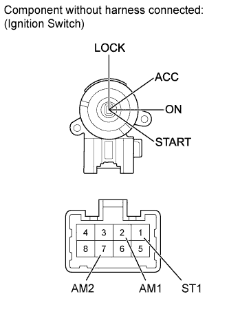
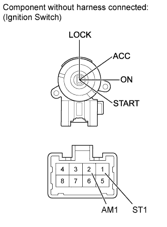
INSPECT IGNITION SWITCH ASSEMBLY
-
Disconnect the ignition switch assembly connector.
-
Measure the resistance according to the value(s) in the table below.
Standard Resistance Tester Connection Switch Condition Specified Condition 2 (AM1) - 1 (ST1) START position Below 1 Ω -
Reconnect the ignition switch assembly connector.
NG
REPLACE IGNITION SWITCH ASSEMBLY
OK
-
-
CHECK HARNESS AND CONNECTOR (IGNITION SWITCH ASSEMBLY - CLUTCH START SWITCH ASSEMBLY)
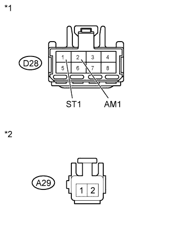
Text in Illustration *1 Front view of wire harness connector:
(to Ignition Switch Assembly)
*2 Front view of wire harness connector:
(to Clutch Start Switch Assembly)
-
Disconnect the ignition switch assembly connector.
-
Disconnect the clutch start switch assembly connector.
-
Measure the resistance according to the value(s) in the table below.
Standard Resistance (Check for Open) Tester Connection Condition Specified Condition D28 - 1 (ST1) - A29-2 Always Below 1 Ω Standard Resistance (Check for Short) Tester Connection Condition Specified Condition D36-3 (STAR) or A29-2 - Body ground Always 10 kΩ or higher -
Reconnect the ignition switch assembly connector.
-
Reconnect the clutch start switch assembly connector.
NG
REPAIR OR REPLACE HARNESS OR CONNECTOR
OK
-
-
CHECK HARNESS AND CONNECTOR (CLUTCH START SWITCH ASSEMBLY- ECM - ST RELAY)
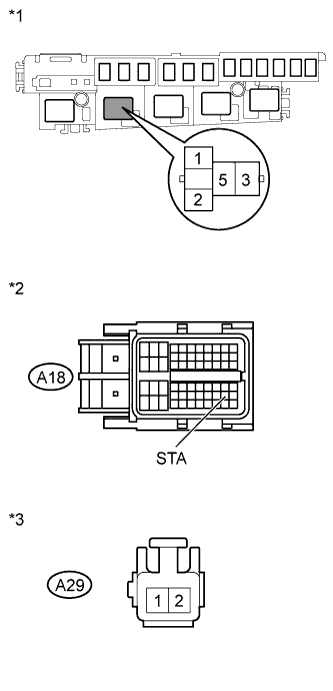
Text in Illustration *1 Front view of wire harness connector:
(to Starter relay)
*2 Front view of wire harness connector:
(to ECM)
*3 Front view of wire harness connector:
(to Clutch start switch Assembly)
-
Remove the ST relay from the engine room relay block.
-
Disconnect the ECM connector.
-
Disconnect the clutch start switch assembly connector.
-
Measure the resistance according to the value(s) in the table below.
Standard Resistance (Check for Open) Tester Connection Condition Specified Condition ST relay terminal 2 - A18-48 (STA) Always Below 1 Ω ST relay terminal 2 - A29-1 Always Below 1 Ω Standard Resistance (Check for Short) Tester Connection Condition Specified Condition A18-48 (STA) or A29-1 - Body ground Always 10 kΩ or higher Result Result Proceed to Outside standard range A Within standard range B -
Reinstall the ST relay.
-
Reconnect the ECM connector.
-
Reconnect the clutch start switch assembly connector.
B
INSPECT BATTERY Click here
A 
REPAIR OR REPLACE HARNESS OR CONNECTOR
-
-
INSPECT PARK/NEUTRAL POSITION SWITCH ASSEMBLY
Text in Illustration *1 Component without harness connected:
(Park/Neutral Position Switch assembly)
-
Disconnect the park/neutral position switch assembly connector.
-
Measure the resistance according to the value(s) in the table below.
Standard Resistance Tester Connection Switch Condition Specified Condition 4 - 5 Shift position P, N Below 1 Ω -
Reconnect the park/neutral start switch assembly connector.
NG
REPAIR OR REPLACE PARK/NEUTRAL POSITION SWITCH ASSEMBLY Click here
OK
-
-
INSPECT IGNITION SWITCH ASSEMBLY
-
Disconnect the ignition switch assembly connector.
-
Measure the resistance according to the value(s) in the table below.
Standard Resistance Tester Connection Switch Condition Specified Condition 2 (AM1) - 1 (ST1) START position Below 1 Ω -
Reconnect the ignition switch assembly connector.
NG
REPLACE IGNITION SWITCH ASSEMBLY
OK
-
-
CHECK HARNESS AND CONNECTOR (IGNITION SWITCH ASSEMBLY - PARK/NEUTRAL POSITION SWITCH)
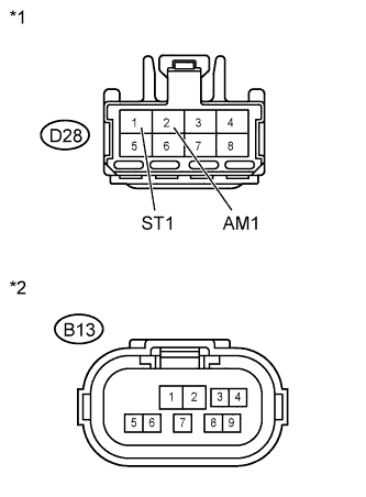
Text in Illustration *1 Front view of wire harness connector:
(to Ignition Switch Assembly)
*2 Front view of wire harness connector:
(to Park/Neutral Position Switch Assembly)
-
Disconnect the ignition switch assembly connector.
-
Disconnect the park/neutral position switch assembly connector.
-
Measure the resistance according to the value(s) in the table below.
Standard Resistance (Check for Open) Tester Connection Condition Specified Condition D28-1 (ST1) - B13-4 Always Below 1 Ω Standard Resistance (Check for Short) Tester Connection Condition Specified Condition D28-1 (ST1) or B13-4 - Body ground Always 10 kΩ or higher -
Reconnect the ignition switch assembly connector.
-
Reconnect the park/neutral position switch assembly connector.
NG
REPAIR OR REPLACE HARNESS OR CONNECTOR
OK
-
-
CHECK HARNESS AND CONNECTOR (PARK/NEUTRAL POSITION SWITCH ASSEMBLY - ECM - ST RELAY)
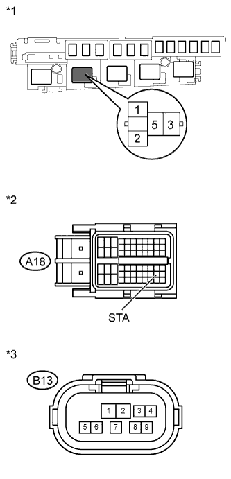
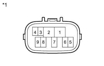
Text in Illustration *1 Front view of wire harness connector:
(to ST relay)
*2 Front view of wire harness connector:
(to ECM)
*3 Front view of wire harness connector:
(to Park/Neutral Position Switch assembly)
-
Remove the ST relay from the engine room relay block.
-
Disconnect the ECM connector.
-
Disconnect the park/neutral position switch assembly connector.
-
Measure the resistance according to the value(s) in the table below.
Standard Resistance (Check for Open) Tester Connection Condition Specified Condition ST relay terminal 2 - A18-48 (STA) Always Below 1 Ω ST relay terminal 2 - B13-5 Always Below 1 Ω Standard Resistance (Check for Short) Tester Connection Condition Specified Condition A18-48 (STA) or B13-5 - Body ground Always 10 kΩ or higher -
Reinstall the ST relay.
-
Reconnect the ECM connector.
-
Reconnect the park/neutral position switch assembly connector.
NG
REPAIR OR REPLACE HARNESS OR CONNECTOR
OK
-
-
INSPECT BATTERY
-
Check that the battery is not depleted.
OK Battery is not depleted.
NG
REPLACE BATTERY
OK
-
-
CHECK BATTERY TERMINAL
-
Check that the battery terminals are not loose or corroded.
OK Battery terminals are not loose or corroded.
NG
REPAIR OR REPLACE BATTERY TERMINAL
OK
CHECK ENTRY AND START SYSTEM
-