SFI SYSTEM, Diagnostic DTC:P0171, P0172

| DTC Code | DTC Name |
|---|---|
| P0171 | System Too Lean (Bank 1) |
| P0172 | System Too Rich (Bank 1) |
DESCRIPTION
The fuel trim is related to the feedback compensation value, not to the basic injection time. The fuel trim consists of both the short-term and long-term fuel trims.
The short-term fuel trim is fuel compensation that is used to constantly maintain the air-fuel ratio at stoichiometric levels. The signal from the Air-Fuel Ratio (A/F) sensor indicates whether the air-fuel ratio is rich or lean compared to the stoichiometric ratio. This triggers a reduction in the fuel injection volume if the air-fuel ratio is rich and an increase in the fuel injection volume if it is lean.
Factors such as individual engine differences, wear over time, and changes in operating environment cause short-term fuel trim to vary from the central value. The long-term fuel trim, which controls overall fuel compensation, compensates for long-term deviations in the fuel trim from the central value caused by the short- term fuel trim compensation.
| DTC No. | DTC Detection Condition | Trouble Area |
|---|---|---|
| P0171 | With warm engine and stable air-fuel ratio feedback, fuel trim considerably in error to lean side (2-trip detection logic) |
|
| P0172 | With warm engine and stable air-fuel ratio feedback, fuel trim considerably in error to rich side (2-trip detection logic) |
|
Tech Tips
-
When DTC P0171 is set, the actual air-fuel ratio is on the lean side. When DTC P0172 is set, the actual air-fuel ratio is on the rich side.
-
If the vehicle runs out of fuel, the air-fuel ratio is lean and DTC P0171 may be set. The MIL is then illuminated.
-
When the total of the short-term and long-term fuel trim values is within the malfunction threshold (and the engine coolant temperature is more than 75°C [167°F]), the system is functioning normally.
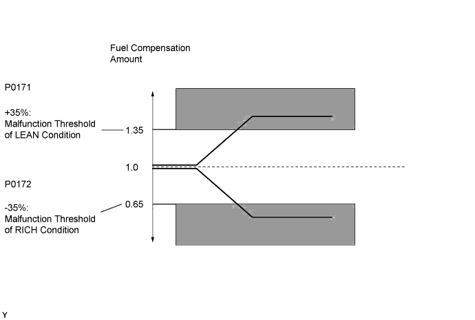
MONITOR DESCRIPTION
Under closed-loop fuel control, fuel injection volumes that deviate from those estimated by the ECM cause changes in the long-term fuel trim compensation value. The long-term fuel trim is adjusted when there are persistent deviations in the short-term fuel trim values. Deviations from the ECM's estimated fuel injection volumes also affect the average fuel trim learning value, which is a combination of the average short-term fuel trim (fuel feedback compensation value) and the average long-term fuel trim (learning value of the air- fuel ratio). If the average fuel trim learning value exceeds the malfunction thresholds, the ECM interprets this a fault in the fuel system and sets a DTC.
Example:
The average fuel trim learning value is more than +35% or less than -35%, and the ECM interprets this as a fuel system malfunction.
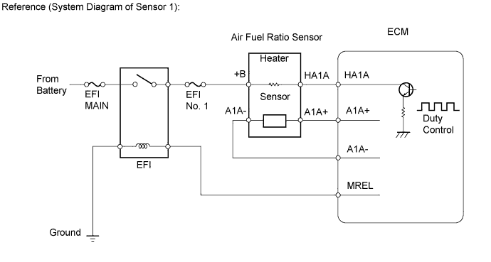
WIRING DIAGRAM
Refer to DTC P2195 Click here.
INSPECTION PROCEDURE
Tech Tips
Intelligent tester only:
Malfunctioning areas can be identified by performing the Control the Injection Volume for A/F sensor function provided in the Active Test. The Control the Injection Volume for A/F sensor function can help to determine whether the Air-Fuel Ratio (A/F) sensor, Heated Oxygen (HO2) sensor and other potential trouble areas are malfunctioning.
The following instructions describe how to conduct the Control the Injection Volume for A/F sensor operation using the intelligent tester.
-
Connect the intelligent tester to the DLC3.
-
Start the engine and turn the tester on.
-
Warm up the engine at an engine speed of 2500 rpm for approximately 90 seconds.
-
Enter the following menus: Powertrain / Engine and ECT / Active Test / Control the Injection Volume for A/F sensor.
-
Perform the Active Test operation with the engine in an idling condition (press the RIGHT or LEFT button to change the fuel injection volume.)
-
Monitor the output voltages of the A/F and HO2 sensors (AF Voltage B1S1 and O2S B1S2) displayed on the tester.
Tech Tips
-
The Control the Injection Volume for A/F sensor operation lowers the fuel injection volume by 12.5% or increases the injection volume by 25%.
-
Each sensor reacts in accordance with increases and decreases in the fuel injection volume.
| Tester Display (Sensor) | Injection Volume | Status | Voltage |
|---|---|---|---|
| AF Voltage B1S1 (A/F) |
+25% | Rich | Less than 3.1 V |
| AF Voltage B1S1 (A/F) |
-12.5% | Lean | More than 3.4 V |
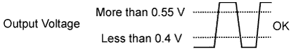
| O2S B1S2 (HO2) |
+25% | Rich | More than 0.55 V |
| O2S B1S2 (HO2) |
-12.5% | Lean | Less than 0.4 V |
Note
The air fuel ratio sensor has an output delay of a few seconds and the heated oxygen sensor has a maximum output delay of approximately 20 seconds.
| Case | A/F Sensor (Sensor 1) Output Voltage | HO2 Sensor (Sensor 2) Output Voltage | Main Suspected Trouble Area |
|---|---|---|---|
| 1 | 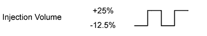 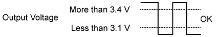 |
 |
- |
| 2 | 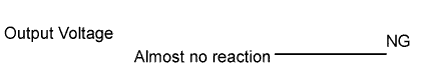 |
|
|
| 3 | |
|
|
| 4 | |
|
|
-
Following the Control the Injection Volume for A/F sensor procedure enables technicians to check and graph the voltage outputs of both the A/F and HO2 sensors.
-
To display the graph, enter the following menus: Powertrain / Engine and ECT / Active Test / Control the Injection Volume for A/F Sensor / A/F Control System / AF Voltage B1S1 and O2S B1S2; then press the View button.
Tech Tips
-
Read freeze frame data using an intelligent tester. Freeze frame data records the engine condition when malfunctions are detected. When troubleshooting, freeze frame data can help determine if the vehicle was moving or stationary, if the engine was warmed up or not, if the air-fuel ratio was lean or rich, and other data from the time the malfunction occurred.
PROCEDURE
-
CHECK ANY OTHER DTCS OUTPUT (IN ADDITION TO P0171 OR P0172)
-
Connect the intelligent tester to the DLC3.
-
Turn the ignition switch to ON.
-
Turn the intelligent tester on.
-
Enter the following menus: Powertrain / Engine and ECT / DTC.
-
Read the DTC.
Result Result Proceed to P0171 or P0172 A P0171 or P0172 and other DTCs B
B 
GO TO DTC CHART Click here
A 
-
-
PERFORM ACTIVE TEST USING INTELLIGENT TESTER (OPERATE EGR VALVE)
-
Connect the intelligent tester to the DLC3.
-
Start the engine and warm it up until the engine coolant temperature reaches 75°C (167°F) or higher.
Tech Tips
The A/C switch and all accessory switches should be off.
-
Turn the tester on.
-
Enter the following menus: Powertrain / Engine and ECT / Active Test / Control the EGR Step Position.
-
Check the MAP in Data List and the idling condition while performing Active Test.
OK MAP and idling condition change in response to EGR step position. Standard - EGR Step Position (Active Test) 0 Steps 0 to 30 Steps 30 to 40 Steps or Higher Idling condition Steady idling Engine changes from steady to rough idling Engine changes from rough idling to engine stall MAP value
(Data List)
28 to 48 kPa
(EGR valve is fully closed)
MAP value is at least +10 to 15 kPa higher than when EGR valve is fully closed 80 to 110 kPa
(After engine stall)
Tech Tips
-
During Active Test, if the idling condition does not change in response to EGR step position, then there is probably a malfunction in EGR valve.
Result Result Proceed to Outside standard range A Within standard range B -
B 
CHECK PCV HOSE CONNECTIONS Click here
A
-
-
CHECK WHETHER DTC OUTPUT RECURS
-
Connect the intelligent tester to the DLC3.
-
Turn the ignition switch to ON.
-
Turn the tester on.
-
Clear the DTC.
-
Turn the ignition switch off and wait for 30 seconds.
-
Start the engine and warm it up until the engine coolant temperature reaches 75°C (167°F) or higher.
Tech Tips
The A/C switch and all accessory switches should be off.
-
Switch the ECM from normal mode to check mode.
-
Drive the vehicle at 60 km/h (37 mph) with the shift lever in B.
CAUTION:
-
Strictly observe speed limits and traffic laws when performing the confirmation drive pattern.
-
-
Perform fuel-cut operation for 5 seconds or more, with the accelerator pedal fully released.
Tech Tips
-
If the deceleration was not completed, perform the confirmation driving pattern again.
-
-
Enter the following menus: Powertrain / Engine and ECT / Utility / All Readiness.
-
Input the DTCs to be confirmed.
-
Check the DTC judgment result.
Result Result Proceed to No output A P0401 B Intelligent Tester Tester Display Description NORMAL
-
DTC judgment completed
-
System normal
ABNORMAL
-
DTC judgment completed
-
System abnormal
INCOMPLETE
-
DTC judgment not completed
-
You should perform driving pattern after confirming DTC enabling conditions
UNKNOWN
-
Unable to perform DTC judgment
-
Number of DTCs which do not fulfill DTC preconditions has reached ECU's memory limit
Tech Tips
-
If the DTC judgment result is INCOMPLETE or UNKNOWN, drive the vehicle again at 60 km/h (37 mph) with the shift lever in B, perform fuel-cut operation for 5 seconds or more with the accelerator pedal fully released, and check the DTC judgment result.
-
B
GO TO DTC CHART Click here
A
-
-
CHECK PCV HOSE CONNECTIONS
OK PCV hose is connected correctly and is not damaged.
NG
REPAIR OR REPLACE PCV HOSE
OK
-
CHECK AIR INDUCTION SYSTEM
-
Check the air induction system for vacuum leak.
OK No leak from air induction system.
NG
REPAIR OR REPLACE AIR INDUCTION SYSTEM
OK
-
-
PERFORM ACTIVE TEST USING INTELLIGENT TESTER (INJECTION VOLUME)
-
Connect an intelligent tester to the DLC3.
-
Start the engine.
-
Turn the tester on.
-
Warm up the engine at an engine speed of 2500 rpm for approximately 90 seconds.
-
Enter the following menus: Powertrain / Engine and ECT / Active Test / Control the Injection Volume for A/F Sensor.
-
Perform the Control the Injection Volume for A/F Sensor operation with the engine in an idling condition (press the RIGHT or LEFT button to change the fuel injection volume).
-
Monitor the voltage outputs of the air fuel ratio sensor and heated oxygen sensor (AFS Voltage B1S1 and O2S B1S2) displayed on the tester.
Tech Tips
-
The Control the Injection Volume for A/F Sensor operation lowers the fuel injection volume by 12.5% or increases the injection volume by 25%.
-
Each sensor reacts in accordance with increases and decreases in the fuel injection volume.
Standard Tester Display
(Sensor)
Injection Volumes Status Voltage AFS Voltage B1S1
(A/F)
+25% Rich Less than 3.1 V AFS Voltage B1S1
(A/F)
-12.5% Lean More than 3.4 V O2S B1S2
(HO2)
+25% Rich More than 0.55 V O2S B1S2
(HO2)
-12.5% Lean Less than 0.4 V Result Status
AFS Voltage B1S1
Status
O2S B1S2
A/F Condition and
A/F Sensor Condition
Misfire Suspected Trouble Area Proceed to Lean/Rich Lean/Rich Normal - - C Lean Lean Actual air fuel ratio lean May occur
-
PCV valve and hose
-
PCV hose connections
-
Fuel injector blockage
-
Gas leak from exhaust system
-
Air induction system
-
Fuel pressure
-
Manifold Absolute Pressure Sensor
-
Engine coolant temperature sensor
A Rich Rich Actual air fuel ratio rich -
-
Fuel injector leak or blockage
-
Gas leak from exhaust system
-
Ignition system
-
Fuel pressure
-
Manifold Absolute Pressure Sensor
-
Engine coolant temperature sensor
Lean Lean/Rich Air fuel ratio sensor malfunction -
-
Air fuel ratio sensor
B Rich Lean/Rich Air fuel ratio sensor malfunction -
-
Air fuel ratio sensor
Lean: During Active Test, the air fuel ratio sensor output voltage (AFS) is consistently more than 3.4 V, and the heated oxygen sensor output voltage (O2S) is consistently less than 0.4 V.
Rich: During Active Test, the AFS is consistently less than 3.1 V, and the O2S is consistently more than 0.55 V.
Lean/Rich: During Active Test, the output voltage of the air fuel ratio sensor and heated oxygen sensor alternates correctly.
-
B
INSPECT AIR FUEL RATIO SENSOR (HEATER RESISTANCE) Click here
C
PERFORM CONFIRMATION DRIVING PATTERN Click here
A
-
-
READ VALUE USING INTELLIGENT TESTER (COOLANT TEMP)
-
Connect an intelligent tester to the DLC3.
-
Turn the ignition switch to ON.
-
Turn the tester on.
-
Enter the following menus: Powertrain / Engine and ECT / Data List / Coolant Temp.
-
Read the Coolant Temp twice, when the engine is both cold and warmed up.
Standard With cold engine: Same as ambient air temperature. With warm engine: 80°C to 100°C (176°C to 212°F).
NG
REPLACE ENGINE COOLANT TEMPERATURE SENSOR Click here
OK
-
-
INSPECT MANIFOLD ABSOLUTE PRESSURE SENSOR
-
Connect the intelligent tester to the DLC3.
-
Turn the tester on.
-
Enter the following menus: Powertrain / Engine and ECT / Data List / MAP.
-
Read the MAP value.
Standard Ignition switch ON 80 to 110 kPa
NG
REPLACE MANIFOLD ABSOLUTE PRESSURE SENSOR Click here
OK
-
-
CHECK FUEL PRESSURE
-
Check the fuel pressure Click here.
NG
REPAIR OR REPLACE FUEL SYSTEM
OK
-
-
CHECK EXHAUST GAS LEAK
OK No gas leak.
NG
REPAIR OR REPLACE EXHAUST SYSTEM
OK
-
CHECK SPARK AND IGNITION
-
Perform a spark test.
CAUTION:
During the test, disconnect all of the fuel injector assembly connectors.
Note
Do not crank the engine for more than 2 seconds.
-
Remove the ignition coil from the cylinder head.
-
Install the spark plug onto the ignition coil.
-
Disconnect the all of the fuel injector assembly connectors.
-
Touch the spark plug to the cylinder head.
-
Crank the engine for less than 2 seconds and check for spark.
OK Sparks jump across electrode gap. -
Reconnect the all of the fuel injector assembly connectors.
-
Reinstall the ignition coil.
Tech Tips
-
If the spark plugs or ignition system malfunctions, engine misfire may occur. The misfire count can be read using an intelligent tester. Enter the following menus: Powertrain / Engine and ECT / Data List / Cylinder #1 Misfire Count - Cylinder #3 Misfire Count.
-
NG
REPAIR OR REPLACE IGNITION SYSTEM
OK
-
-
INSPECT FUEL INJECTOR ASSEMBLY (INJECTION AND VOLUME)
Tech Tips
-
Refer to the fuel injector inspection procedure Click here.
-
If the fuel injectors malfunction, engine misfire may occur. The misfire count can be read using an intelligent tester. Enter the following menus: Powertrain / Engine and ECT / Data List / Cylinder #1 Misfire Count - Cylinder #3 Misfire Count.
NG
REPLACE FUEL INJECTOR ASSEMBLY Click here
OK
-
-
INSPECT AIR FUEL RATIO SENSOR (HEATER RESISTANCE)
-
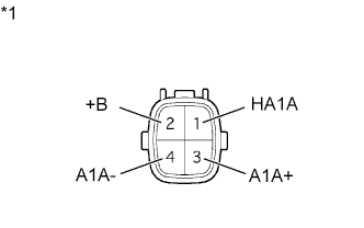
Text in Illustration *1 Component without harness connected:
(Air Fuel Ratio Sensor)
Disconnect the air fuel ratio sensor connector.
-
Measure the resistance according to the value(s) in the table below.
Standard Resistance Tester Connection Condition Specified Condition 1 (HA1A) - 2 (+B) 20°C (68°F) 1.8 to 3.4 Ω 1 (HA1A) - 3 (A1A+) Always 10 kΩ or higher -
Reconnect the air fuel ratio sensor connector.
NG
REPLACE AIR FUEL RATIO SENSOR Click here
OK
-
-
CHECK HARNESS AND CONNECTOR (AIR FUEL RATIO SENSOR - ECM)
-
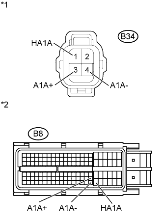
Text in Illustration *1 Front view of wire harness connector:
(to Air Fuel Ratio Sensor)
*2 Front view of wire harness connector:
(to ECM)
Disconnect the air fuel ratio sensor connector.
-
Disconnect the ECM connector.
-
Measure the resistance according to the value(s) in the table below.
Standard Resistance (Check for Open) Tester Connection Condition Specified Condition B34-1 (HA1A) - B8-104 (HT1A) Always Below 1 Ω B34-3 (A1A+) - B8-103 (A1A+) Always Below 1 Ω B34-4 (A1A-) - B8-126 (A1A-) Always Below 1 Ω Standard Resistance (Check for Short) Tester Connection Condition Specified Condition B34-1 (HA1A) or B8-104 (HT1A) - Body ground Always 10 kΩ or higher B34-3 (A1A+) or B8-103 (A1A+) - Body ground Always 10 kΩ or higher B34-4 (A1A-) or B8-126 (A1A-) - Body ground Always 10 kΩ or higher -
Reconnect the ECM connector.
-
Reconnect the air fuel ratio sensor connector.
NG
REPAIR OR REPLACE HARNESS OR CONNECTOR
OK
-
-
REPLACE AIR FUEL RATIO SENSOR
-
Replace the air fuel ratio sensor Click here.
NEXT
-
-
PERFORM CONFIRMATION DRIVING PATTERN
-
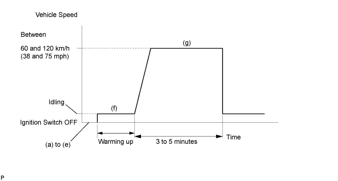
-
(a) Connect an intelligent tester to the DLC3.
-
(b) Turn the ignition switch to ON.
-
(c) Turn the tester on.
-
(d) Clear DTCs Click here.
-
(e) Switch the ECM from normal mode to check mode using the tester Click here.
-
(f) Start the engine and warm it up with all the accessories switched off.
-
(g) Drive the vehicle at between 60 km/h and 120 km/h (38 mph and 75 mph) and at an engine speed of between 1400 rpm and 3200 rpm for 3 to 5 minutes.
Tech Tips
If the system is still malfunctioning, the MIL will be illuminated during step (g).
Note
If the conditions in this test are not strictly followed, no malfunction will be detected.
NEXT
-
-
CHECK WHETHER DTC OUTPUT RECURS (DTC P0171 OR P0172)
-
Connect an intelligent tester to the DLC3.
-
Turn the ignition switch to ON.
-
Turn the tester on.
-
Enter the following menus: Powertrain / Engine and ECT / DTC.
-
Read DTCs.
Result Result Proceed to No output A P0171 or P0172 B
B
REPLACE ECM Click here
A 
END
-