RELAY ON-VEHICLE INSPECTION

-
REMOVE NO. 1 RELAY BLOCK COVER
-
REMOVE INTEGRATION NO.2 RELAY
-
Remove the fusible link cover.
-
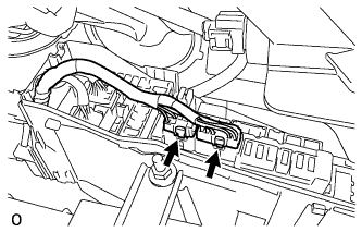
Disconnect the 2 connectors from the integration relay.
-
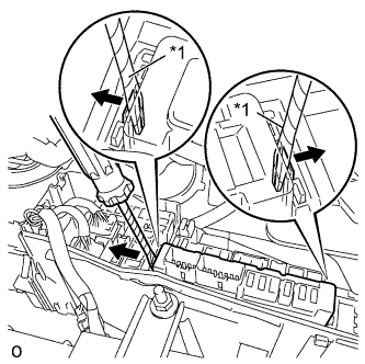
Text in Illustration *1 Protective tape Using a screwdriver with its tip wrapped with the protective tape, disengage the 2 claws.
-
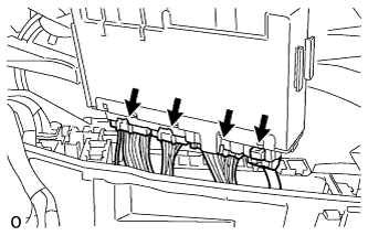
Separate the 4 connectors and remove the integration relay.
-
-
INSPECT INTEGRATION NO.1 RELAY (for 1KR-FE)
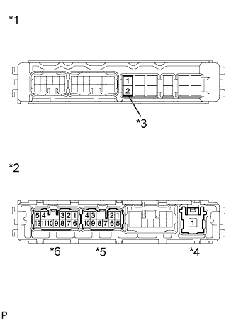
Text in Illustration *1 Fuse Side *2 Connector Side *3 Horn Fuse *4 Connector A *5 Connector C *6 Connector D
-
Check the resistance.
-
Remove the horn fuse.
-
Measure the resistance according to the value(s) in the table below.
Standard Resistance Tester Connection Condition Specified Condition 1 - 2 Always Below 1 Ω -
Install the horn fuse.
If the result is not as specified, replace the horn fuse.
-
-
Check the resistance.
-
Measure the resistance according to the value(s) in the table below.
Standard Resistance Tester Connection Condition Specified Condition A1 - C6 Always 10 kΩ or higher A1 - C7 -
Measure the voltage according to the value(s) in the table below.
Standard Voltage Tester Connection Condition Specified Condition A1 - C6 When battery voltage is applied to terminal A1 and D9 Below 1 V A1 - C7 If the result is not as specified, replace the relay.
-
-
-
INSPECT INTEGRATION NO.1 RELAY (for 1ND-TV)
Text in Illustration *1 Fuse Side *2 Connector Side *3 Horn Fuse *4 Connector A *5 Connector C *6 Connector D
-
Check the resistance.
-
Remove the horn fuse.
-
Measure the resistance according to the value(s) in the table below.
Standard Resistance Tester Connection Condition Specified Condition 1 - 2 Always Below 1 Ω -
Install the horn fuse.
If the result is not as specified, replace the horn fuse.
-
-
Check the resistance.
-
Measure the resistance according to the value(s) in the table below.
Standard Resistance Tester Connection Condition Specified Condition A1 - C1 Always 10 kΩ or higher A1 - C5 -
Measure the voltage according to the value(s) in the table below.
Standard Voltage Tester Connection Condition Specified Condition A1 - C1 When battery voltage is applied to terminal A1 and D11 Below 1 V A1 - C5 If the result is not as specified, replace the relay.
-
-
-
INSTALL INTEGRATION NO.2 RELAY
-
Connect the 4 connectors to the integration relay.
-
Engage the 2 claws and install the integration relay.
-
Connect the 2 connectors to the integration relay.
-
Install the fusible link cover.
-
-
INSTALL NO.1 RELAY BLOCK COVER