REAR COMBINATION LIGHT ASSEMBLY ON-VEHICLE INSPECTION

-
INSPECT REAR COMBINATION LIGHT ASSEMBLY LH
-
Disconnect the connector from the rear combination light.
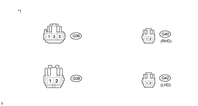
Text in Illustration *1 Front view of wire harness connector
(to rear Combination light Assembly LH)
-
Measure the voltage and resistance according to the value(s) in the table below.
Standard Tester Connection Switch Condition Specified Condition G36-2 - G36-1 Light control switch OFF Below 1 Ω Light control switch in TAIL 11 to 14 V G36-3 - G36-1 Brake pedal released Below 1 Ω Brake pedal depressed 11 to 14 V G38-1 - G38-2 Turn signal switch OFF Below 1 Ω Ignition switch ON and Turn signal switch in LH 11 to 14 V (60 to 120 times per minute) G40-1 - G40-2 Shift lever not in R Below 1 Ω Shift lever in R 11 to 14 V G42-1 - G42-2 Rear fog light switch OFF Below 1 Ω Rear fog light switch ON 11 to 14 V
-
-
INSPECT REAR COMBINATION LIGHT ASSEMBLY RH
-
Disconnect the connector from the rear combination light.
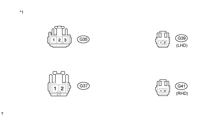
Text in Illustration *1 Front view of wire harness connector
(to rear Combination light Assembly RH)
-
Measure the voltage and resistance according to the value(s) in the table below.
Standard Tester Connection Switch Condition Specified Condition G35-2 - G35-1 Light control switch OFF Below 1 Ω Light control switch in TAIL 11 to 14 V G35-3 - G35-1 Brake pedal released Below 1 Ω Brake pedal depressed 11 to 14 V G37-1 - G37-2 Turn signal switch OFF Below 1 Ω Ignition switch ON and turn signal switch in RH 11 to 14 V (60 to 120 times per minute) G39-1 - G39-2 Shift lever not in R Below 1 Ω Shift lever in R 11 to 14 V G41-1 - G41-2 Rear fog light switch OFF Below 1 Ω Rear fog light switch ON 11 to 14 V
-