LIGHTING SYSTEM IG Signal Circuit
DESCRIPTION
-
The main body ECU receives IG signal to control the exterior light control system as shown below:
-
Automatic light control
-
Light auto turn off control
-
Daytime running light control
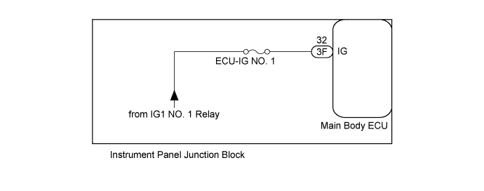
WIRING DIAGRAM
INSPECTION PROCEDURE
Note
Inspect the fuses for circuit related to this system before performing the following inspection procedure.
PROCEDURE
-
READ VALUE USING INTELLIGENT TESTER
-
Connect the intelligent tester to the DLC3.
-
Turn the ignition switch to ON.
-
Turn the tester on.
-
Enter the following menus: Body / Main Body / Data List.
-
According to the display on the tester, read the Data List.
Main Body Tester Display Measurement Item/Range Normal Condition Diagnostic Note IG SW Ignition switch or engine switch IG signal
ON or OFF
ON: Ignition switch ON
OFF: Ignition switch off
- OK Normal conditions listed above are displayed.
NG 
REPLACE MAIN BODY ECU Click here
OK 
PROCEED TO NEXT SUSPECTED AREA SHOWN IN PROBLEM SYMPTOMS TABLE Click here
-
-
REPLACE MAIN BODY ECU
-
Temporarily replace the main body ECU with a new or normally functioning one Click here.
NEXT 
-
-
READ VALUE USING INTELLIGENT TESTER
-
Connect the intelligent tester to the DLC3.
-
Turn the ignition switch to ON.
-
Turn the tester on.
-
Enter the following menus: Body / Main Body / Data List.
-
According to the display on the tester, read the Data List.
Main Body Tester Display Measurement Item/Range Normal Condition Diagnostic Note IG SW Ignition switch or engine switch IG signal
ON or OFF
ON: Ignition switch ON
OFF: Ignition switch off
- OK Normal conditions listed above are displayed.
NG 
REPLACE INSTRUMENT PANEL JUNCTION BLOCK
OK
END (MAIN BODY ECU DEFECTIVE)
-