LIGHTING SYSTEM TERMINALS OF ECU

-
CHECK MAIN BODY ECU AND INSTRUMENT PANEL JUNCTION BLOCK (w/ Daytime Running Light System or w/ Automatic Light Control System)
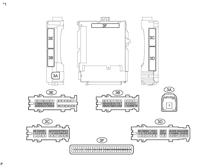
Text in Illustration *1 Instrument Panel Junction Block 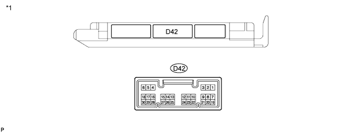
Text in Illustration *1 Main body ECU (w/ Theft Deterrent System) 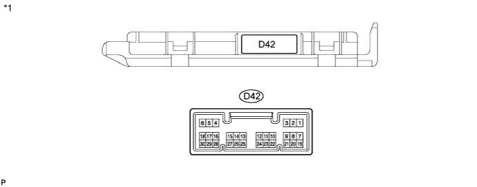
Text in Illustration *1 Main body ECU (w/o Theft Deterrent System)
-
Remove the main body ECU.
-
Measure the resistance and voltage between each terminal of the wire harness side connectors and body ground.
Terminal No. (Symbol) Wiring Color Terminal Description Condition Specified Condition 3F-11 (GND1) - Body ground - Ground Always Below 1 Ω 3F-29 (ACC)*1 - Body ground - Ignition power supply (ACC signal) Ignition switch ACC → off 11 to 14 V → Below 1 V 3F-30 (BECU) - Body ground - +B (power system signal system) power supply Always 11 to 14 V 3F-32 (IG)*1 - Body ground - Ignition power supply (IG signal) Ignition switch ON → off 11 to 14 V → Below 1 V
-
*1: w/o Entry and Start System
If the result is not as specified, there may be a malfunction on the wire harness side.
-
-
Reinstall the main body ECU.
-
Measure the voltage between each terminal of the wire harness side connectors and body ground.
Terminal No. (Symbol) Wiring Color Terminal Description Condition Specified Condition D42-1 (RFOG) - Body ground GR - Body ground Rear fog light switch input Rear fog light switch ON Below 1 V Rear fog light switch OFF Pulse generation D42-3 (HAZ) - Body ground R - Body ground Hazard warning signal switch input Hazard warning signal switch ON Below 1 V Hazard warning signal switch OFF Pulse generation D42-5 (HU) - Body ground W - Body ground Dimmer switch HIGH signal input Dimmer switch in HIGH Below 1 V Dimmer switch in LOW Pulse generation D42-8 (HF) - Body ground SB - Body ground Dimmer switch HIGH FLASH signal input Dimmer switch in HIGH FLASH position Below 1 V Dimmer switch not in HIGH FLASH position Pulse generation D42-13 (CANL) - Body ground W - Body ground CAN communication line L Ignition switch ON Pulse generation Ignition switch off Below 1 V D42-14 (CANH) - Body ground R - Body ground CAN communication line H Ignition switch ON Pulse generation Ignition switch off Below 1 V D42-20 (CLTB) - Body ground R - Body ground Automatic light control sensor power supply output Ignition switch ON and light control switch in AUTO 11 to 14 V Ignition switch off Below 1 V D42-21 (CLTS) - Body ground Y - Body ground Automatic light control sensor signal input Automatic light control system operates Pulse generation
(See waveform 1)
Ignition switch off Below 1 V D42-22 (CLTE) - Body ground GR - Body ground Automatic light control sensor ground Always Below 1 Ω D42-27 (FFOG) - Body ground P - Body ground Front fog light switch input Front fog light switch ON Below 1 V Front fog light switch OFF Pulse generation D42-28 (A) - Body ground GR - Body ground Light control switch AUTO signal input Light control switch in AUTO Below 1 V Light control switch not in AUTO Pulse generation D42-29 (HEAD) - Body ground L - Body ground Light control switch HEAD signal input Light control switch in HEAD Below 1 V Light control switch not in HEAD Pulse generation D42-30 (TAIL) - Body ground Y - Body ground Light control switch TAIL signal input Light control switch in TAIL or HEAD Below 1 V Light control switch in neither TAIL nor HEAD 11 to 14 V 3B-25 (DIM) - Body ground G-Y - Body ground High beam headlight relay drive output Dimmer switch in HIGH or HIGH FLASH Below 1 V Dimmer switch in LOW 11 to 14 V 3C-29 (FFGO) - Body ground R - Body ground Front fog light relay drive output Light control switch in TAIL and front fog light switch ON Below 1 V Light control switch in TAIL and front fog light switch OFF 11 to 14 V 3B-34 (HRLY) - Body ground W-L - Body ground Headlight relay drive output Light control switch in HEAD Below 1 V Light control switch not in HEAD 11 to 14 V If the result is not as specified, the main body ECU may have a malfunction.
-
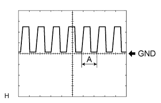
Waveform 1: Using an oscilloscope
Terminal Name D42-21 (CLTS) - Body ground Tester Range 5 V/DIV, 5 ms/DIV Condition Ignition switch ON and light control switch in AUTO Tech Tips
If the ambient light becomes brighter, width A becomes narrower.
-
-