HOOD LOCK CONTROL CABLE ASSEMBLY INSTALLATION

-
INSTALL HOOD LOCK CONTROL CABLE ASSEMBLY (for LHD)
-
Pass the hood lock control cable into the engine compartment.
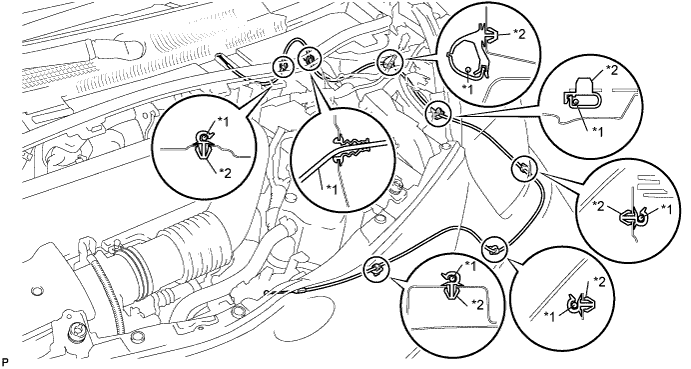
Area Part Name Area Part Name *1 Hood lock control cable *2 Clamp -
Connect the clamps as shown in the illustration.
-
-
INSTALL HOOD LOCK CONTROL CABLE ASSEMBLY (for RHD)
-
Pass the hood lock control cable into the engine compartment.
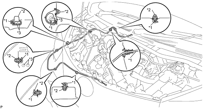
Area Part Name Area Part Name *1 Hood lock control cable *3 Washer hose *2 Clamp - - -
Connect the clamps as shown in the illustration.
-
-
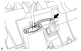
INSTALL HOOD LOCK CONTROL LEVER
-
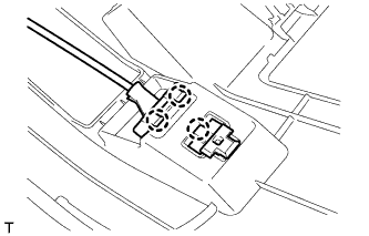
Connect the hood lock control cable.
-
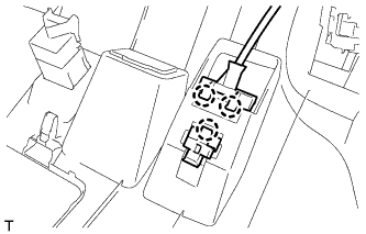
Engage the 3 claws and install the hood lock control lever.
-
-
INSTALL LOWER NO.1 INSTRUMENT PANEL FINISH PANEL
-
Engage the 3 claws and connect the hood lock control lever.
-
Connect the connector.
-
Engage the 2 claws and connect the DLC3 connector.
-
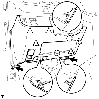
Engage the 2 claws and 7 clips.
-
Install the lower No. 1 instrument panel finish panel with the 2 <C> bolts.
-
-
INSTALL FRONT DOOR OPENING TRIM WEATHERSTRIP
-
Install the front door opening trim weatherstrip.
-
-
INSTALL COWL SIDE TRIM BOARD
Tech Tips
Use the same procedure as for the RH side Click here.
-
INSTALL FRONT DOOR SCUFF PLATE
Tech Tips
Use the same procedure as for the RH side Click here.
-
INSTALL HOOD LOCK ASSEMBLY (w/o Engine Hood Courtesy Switch)
-
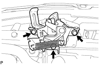
Apply MP grease to the sliding areas of the lock.
-
Connect the hood lock control cable.
-
Install the hood lock assembly with the 3 bolts.
- Torque:
- 7.5 N*m { 76 kgf*cm, 66 in.*lbf }
-
-
INSTALL HOOD LOCK ASSEMBLY (w/ Engine Hood Courtesy Switch)
-
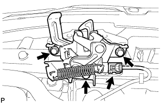
Apply MP grease to the sliding areas of the lock.
-
Connect the hood lock control cable.
-
Install the hood lock assembly with the 3 bolts.
- Torque:
- 7.5 N*m { 76 kgf*cm, 66 in.*lbf }
-
Connect the connector.
-
-
INSPECT HOOD SUB-ASSEMBLY
-
Check that the clearance measurements are within the standard ranges.
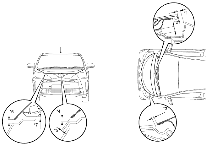
Standard Area Measurement Area Measurement *1 5.0 to 11.0 mm
(0.197 to 0.433 in.)
*5 1.6 mm
(0.063 in.)
*2 10.5 mm
(0.413 in.)
*6 4.5 to 7.5 mm
(0.177 to 0.295 in.)
*3 2.3 to 5.3 mm
(0.091 to 0.209 in.)
*7 2.9 to 5.9 mm
(0.114 to 0.232 in.)
*4 4.5 to 7.5 mm
(0.177 to 0.295 in.)
- -
-
-
ADJUST HOOD SUB-ASSEMBLY
-
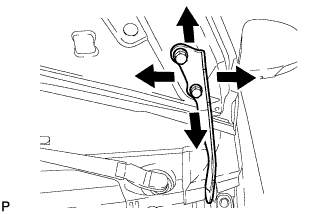
Loosen the 4 hood side hinge bolts.
-
Move the hood to adjust the clearance to within the standard range Click here.
-
Tighten the 4 hood side hinge bolts after the adjustment.
- Torque:
- 13 N*m { 133 kgf*cm, 10 ft.*lbf }
-
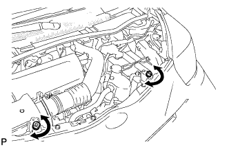
Adjust the height of the hood front end by turning the cushion rubber Click here.
Tech Tips
The cushion rubber can be raised and lowered by turning it.
-
Adjust the hood lock.
-
Loosen the 3 bolts.
-
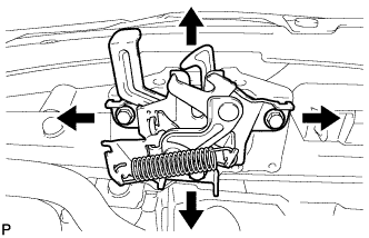
Adjust the hood lock position so that the striker can enter it smoothly.
-
Tighten the 3 bolts after the adjustment.
- Torque:
- 7.5 N*m { 76 kgf*cm, 66 in.*lbf }
-
-
-
INSTALL FRONT FENDER SPLASH SHIELD SUB-ASSEMBLY
-
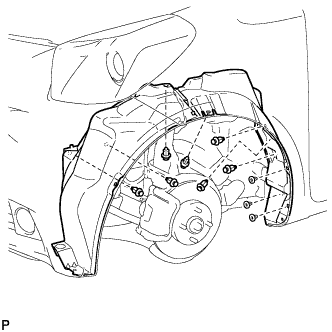
Install the front fender splash shield with the 3 grommets.
-
Install the 7 clips.
-
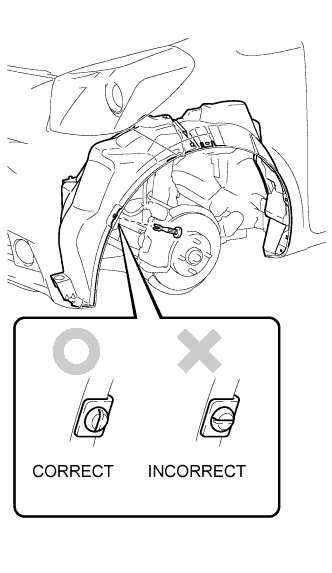
Install the pin hold clip.
Note
Install the pin hold clip with the slot aligned vertically. Do not rotate the clip after inserting it. After installation, confirm that the slot is vertical.
-
-
INSTALL FENDER REAR PLATE MUDGUARD
-
Remove the fender rear plate mudguard Click here.
-
-
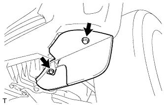
INSTALL FRONT WHEEL OPENING EXTENSION PAD
-
Install the front wheel opening extension pad with the 2 screws.
-
-
INSTALL FRONT WHEEL