WINDOW DEFOGGER SYSTEM Rear Window Defogger System does not Operate
DESCRIPTION
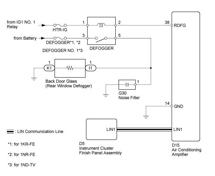
When the rear defogger switch is turned on, a rear defogger activation request signal is transmitted from the instrument cluster finish panel assembly to the air conditioning amplifier. Upon receipt of the signal, the air conditioning amplifier turns on the defogger relay to activate the rear window defogger system.
WIRING DIAGRAM
INSPECTION PROCEDURE
Note
Inspect the fuses for circuits related to this system before performing the following inspection procedure.
PROCEDURE
-
PERFORM ACTIVE TEST USING INTELLIGENT TESTER (DEFOGGER RELAY)
-
Connect the intelligent tester to the DLC3.
-
Turn the ignition switch to ON.
-
Turn the tester on.
-
Enter the following menus: Body / Air Conditioner / Active Test.
-
According to the display on the tester, perform the Active Test.
Air Conditioner Tester Display Test Part Control Range Diagnostic Note Defogger Relay (Rear) Defogger relay OFF or ON - OK Defogger operates on and off.
NG 
CHECK HARNESS AND CONNECTOR (DEFOGGER RELAY - BACK DOOR GLASS (REAR DEFOGGER)) Click here
OK 
-
-
CHECK AIR CONDITIONING SYSTEM (LIN COMMUNICATION)
-
Operate the switch to change the instrument cluster finish panel set temperature and check that the temperature at the outlets changes.
OK The outlet temperature changes in accordance with the instrument cluster finish panel display.
NG 
GO TO AIR CONDITIONING CONTROL PANEL CIRCUIT Click here
OK
-
-
REPLACE INSTRUMENT CLUSTER FINISH PANEL ASSEMBLY
-
Temporarily replace the instrument cluster finish panel assembly with a new or normally functioning one Click here.
NEXT
-
-
CHECK INSTRUMENT CLUSTER FINISH PANEL ASSEMBLY (OPERATION)
-
Check that the malfunction disappears.
OK Malfunction disappears.
NG
REPLACE AIR CONDITIONING AMPLIFIER Click here
OK 
END (INSTRUMENT CLUSTER FINISH PANEL ASSEMBLY IS DEFECTIVE)
-
-
CHECK HARNESS AND CONNECTOR (DEFOGGER RELAY - BACK DOOR GLASS (REAR DEFOGGER))
-
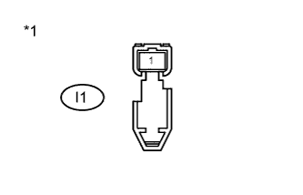
Text in Illustration *1 Front view of wire harness connector
(to Back Door Glass (Rear Defogger))
Disconnect the I1 rear defogger connector.
-
Measure the voltage according to the value(s) in the table below.
Standard Voltage Tester Connection Switch Condition Specified Condition I1-1 - Body ground Engine running
Rear defogger switch ON
11 to 14 V -
Reconnect the rear defogger connector.
NG
INSPECT DEFOGGER RELAY Click here
OK
-
-
CHECK HARNESS AND CONNECTOR (REAR WINDOW DEFOGGER - BODY GROUND)
-
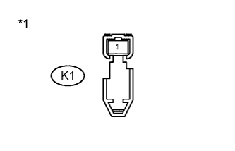
Text in Illustration *1 Front view of wire harness connector
(to Back Door Glass (Rear Defogger))
Disconnect the K1 rear defogger connector.
-
Measure the resistance according to the value(s) in the table below.
Standard Resistance Tester Connection Condition Specified Condition K1-1- Body ground Always Below 1 Ω -
Reconnect the rear defogger connector.
NG
REPAIR OR REPLACE HARNESS OR CONNECTOR
OK
REPAIR OR REPLACE BACK DOOR GLASS (REAR WINDOW DEFOGGER) Click here
-
-
INSPECT DEFOGGER RELAY
-
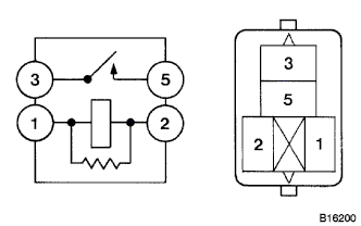
Remove the defogger relay from the engine room relay block.
-
Measure the resistance according to the value(s) in the table below.
Standard Resistance Tester Connection Condition Specified Condition 3 - 5 When battery voltage is not applied between terminals 1 and 2 10 kΩ or higher When battery voltage is applied to terminals 1 and 2 Below 1 Ω -
Reinstall the defogger relay.
NG
REPLACE DEFOGGER RELAY
OK
-
-
CHECK HARNESS AND CONNECTOR (DEFOGGER RELAY - BATTERY)
-
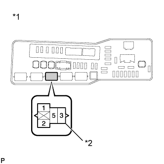
Text in Illustration *1 Component without relay connected
(Engine Room Relay Block)
*2 Defogger Relay Remove the defogger relay from the engine room relay block.
-
Measure the voltage according to the value(s) in the table below.
Standard Voltage Tester Connection Switch Condition Specified Condition Defogger relay terminal 1 - Body ground Ignition switch ON 11 to 14 V Defogger relay terminal 3 - Body ground Always 11 to 14 V -
Reinstall the defogger relay.
NG
REPAIR OR REPLACE HARNESS OR CONNECTOR
OK
-
-
CHECK HARNESS AND CONNECTOR (DEFOGGER RELAY - AIR CONDITIONING AMPLIFIER)
-
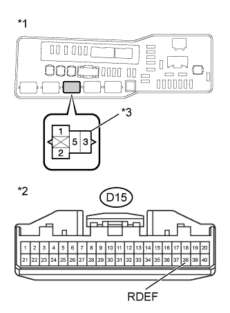
Text in Illustration *1 Component without relay connected
(Engine Room Relay Block)
*2 Front view of wire harness connectors
(to Air Conditioning Amplifier)
*3 Defogger Relay Remove the defogger relay from the engine room relay block.
-
Disconnect the D15 air conditioning amplifier connector.
-
Measure the resistance according to the value(s) in the table below.
Standard Resistance Tester Connection Condition Specified Condition Defogger relay terminal 2 - D15-38 (RDEF) Always Below 1 Ω -
Reconnect the air conditioning amplifier connector.
-
Reinstall the defogger relay.
NG
REPAIR OR REPLACE HARNESS OR CONNECTOR
OK
-
-
CHECK HARNESS AND CONNECTOR (REAR WINDOW DEFOGGER - DEFOGGER RELAY, BODY GROUND)
-
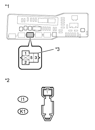
Text in Illustration *1 Component without relay connected
(Engine Room Relay Block)
*2 Front view of wire harness connector
(to Rear Window Defogger)
*3 Defogger Relay Disconnect the I1 and K1 defogger connectors.
-
Remove the defogger relay from the engine room relay block.
-
Measure the resistance according to the value(s) in the table below.
Standard Resistance Tester Connection Condition Specified Condition I1-1 - Defogger relay terminal 5 Always Below 1 Ω I1-1 - Body ground Always 10 kΩ or higher K1-1 - Body ground Always Below 1 Ω -
Reinstall the defogger relay.
-
Reconnect the defogger connectors.
NG
REPAIR OR REPLACE HARNESS OR CONNECTOR
OK
REPLACE AIR CONDITIONING AMPLIFIER Click here
-