POWER WINDOW CONTROL SYSTEM Driver Side Power Window does not Operate with Power Window Master Switch
DESCRIPTION
-
If the manual UP/DOWN function does not operate, there may be a malfunction in the power window regulator master switch, the power window regulator motor, the harness or the connector.
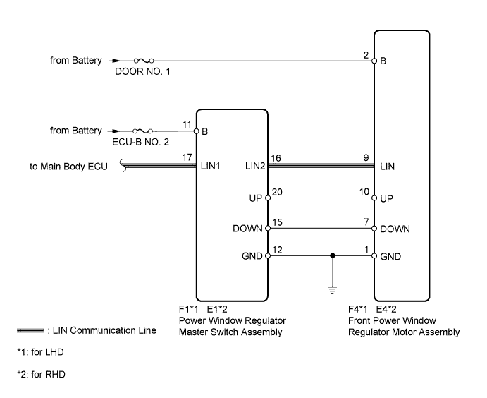
WIRING DIAGRAM
INSPECTION PROCEDURE
Note
Inspect the fuses for circuit related to this system before performing the following inspection procedure.
PROCEDURE
-
CHECK LIN COMMUNICATION SYSTEM
-
Check for LIN communication system DTCs related to the power window control system Click here.
OK LIN communication system DTCs are not output.
NG 
GO TO LIN COMMUNICATION SYSTEM Click here
OK 
-
-
CHECK FOR DTC (B2312)
-
Check if DTC B2312 is output Click here.
OK DTC B2312 is not output.
NG
GO TO DTC (B2312) Click here
OK
-
-
READ VALUE USING INTELLIGENT TESTER (D-DOOR MOTOR)
-
Connect the intelligent tester to the DLC3.
-
Turn the ignition switch to ON.
-
Turn the tester on.
-
Enter the following menus: Body / D-Door Motor / Data List.
-
According to the display on the tester, read the Data List.
D-Door Motor Tester Display Measurement Item/Range Normal Condition Diagnostic Note D Door P/W Up SW Driver side power window MANUAL UP switch signal / ON or OFF ON: Driver side power window manual UP switch operated
OFF: Driver side power window switch not operated
- D Door P/W Down SW Driver side power window MANUAL DOWN switch signal / ON or OFF ON: Driver side power window manual DOWN switch operated
OFF: OFF: Driver side power window switch not operated
- OK The tester display changes normally when master switch is operated.
NG 
CHECK HARNESS AND CONNECTOR (POWER WINDOW REGULATOR MASTER SWITCH - BATTERY, BODY GROUND) Click here
OK 
REPLACE FRONT DOOR WINDOW REGULATOR SUB-ASSEMBLY Click here
-
-
CHECK HARNESS AND CONNECTOR (POWER WINDOW REGULATOR MASTER SWITCH - BATTERY, BODY GROUND)
-
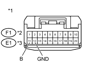
Text in Illustration *1 Front view of wire harness connector
(to Power Window Regulator Master Switch Assembly)
*2 for LHD *3 for RHD Disconnect the F1 or E1 power window regulator master switch assembly connector.
-
Measure the voltage according to the value(s) in the table below.
Standard Voltage for LHD Tester Connection Condition Specified Condition F1-11 (B) - Body ground Always 11 to 14 V for RHD Tester Connection Condition Specified Condition E1-11 (B) - Body ground Always 11 to 14 V -
Measure the resistance according to the value(s) in the table below.
Standard Resistance for LHD Tester Connection Condition Specified Condition F1-12 (GND) - Body ground Always Below 1 Ω for RHD Tester Connection Condition Specified Condition E1-12 (GND) - Body ground Always Below 1 Ω -
Reconnect the power window regulator master switch assembly connector.
NG
REPAIR OR REPLACE HARNESS OR CONNECTOR
OK
-
-
CHECK HARNESS AND CONNECTOR (FRONT POWER WINDOW REGULATOR MOTOR - BATTERY, BODY GROUND)
-
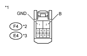
Text in Illustration *1 Front view of wire harness connector
(to Front Power Window Regulator Motor Assembly)
*2 for LHD *3 for RHD Disconnect the F4 or E4 front power window regulator motor assembly connector.
-
Measure the voltage according to the value(s) in the table below.
Standard Voltage for LHD Tester Connection Condition Specified Condition F4-2 (B) - Body ground Always 11 to 14 V for RHD Tester Connection Condition Specified Condition E4-2 (B) - Body ground Always 11 to 14 V -
Measure the resistance according to the value(s) in the table below.
Standard Resistance for LHD Tester Connection Condition Specified Condition F4-1 (GND) - Body ground Always Below 1 Ω for RHD Tester Connection Condition Specified Condition E4-1 (GND) - Body ground Always Below 1 Ω -
Reconnect the front power window regulator motor assembly connector.
NG
REPAIR OR REPLACE HARNESS OR CONNECTOR
OK
-
-
CHECK HARNESS AND CONNECTOR (POWER WINDOW MASTER SWITCH - POWER WINDOW REGULATOR MOTOR)
-
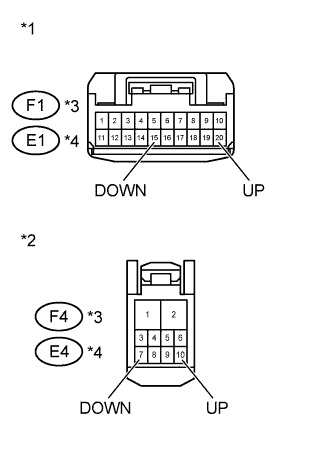
Text in Illustration *1 Front view of wire harness connector
(to Power Window Regulator Master Switch Assembly)
*2 Front view of wire harness connector
(to Front Power Window Regulator Motor Assembly)
*3 for LHD *4 for RHD Disconnect the F1 or E1 power window regulator master switch assembly connector.
-
Disconnect the F4 or E4 front power window regulator motor assembly connector.
-
Measure the resistance according to the value(s) in the table below.
Standard Resistance for LHD Tester Connection Condition Specified Condition F1-20 (UP) - F4-10 (UP) Always Below 1 Ω F1-15 (DOWN) - F4-7 (DOWN) Always Below 1 Ω F1-20 (UP) - Body ground Always 10 kΩ or higher F1-15 (DOWN) - Body ground Always 10 kΩ or higher for RHD Tester Connection Condition Specified Condition E1-20 (UP) - E4-10 (UP) Always Below 1 Ω E1-15 (DOWN) - E4-7 (DOWN) Always Below 1 Ω E1-20 (UP) - Body ground Always 10 kΩ or higher E1-15 (DOWN) - Body ground Always 10 kΩ or higher -
Reconnect the front power window regulator motor assembly connector.
-
Reconnect the power window regulator master switch assembly connector.
NG
REPAIR OR REPLACE HARNESS OR CONNECTOR
OK
-
-
INSPECT FRONT DOOR WINDOW REGULATOR SUB-ASSEMBLY (WINDOW REGULATOR MOTOR)
-
Remove the front door window regulator sub-assembly Click here.
-
Apply battery voltage to the regulator motor and check the operation of the regulator motor.
-
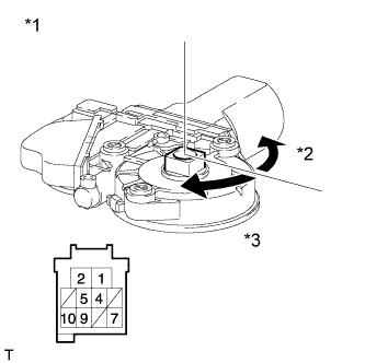
Text in Illustration *1 Component without harness connected
(Front Power Window Regulator Motor Assembly LH)
*2 Counterclockwise *3 Clockwise for LHD:
OK Measurement condition Specified Condition Battery positive (+) → Terminal 2
Battery positive (-) → Terminal 1
Motor gear rotates clockwise Battery positive (+) → Terminal 1
Battery positive (-) → Terminal 2
Motor gear rotates counterclockwise -
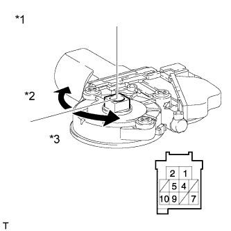
Text in Illustration *1 Component without harness connected
(Front Power Window Regulator Motor Assembly RH)
*2 Clockwise *3 Counterclockwise for RHD:
OK Measurement condition Specified Condition Battery positive (+) → Terminal 1
Battery positive (-) → Terminal 2
Motor gear rotates clockwise Battery positive (+) → Terminal 2
Battery positive (-) → Terminal 1
Motor gear rotates counterclockwise
-
-
Reinstall the front door window regulator sub-assembly.
NG
REPLACE FRONT DOOR WINDOW REGULATOR SUB-ASSEMBLY Click here
OK
REPLACE POWER WINDOW REGULATOR MASTER SWITCH ASSEMBLY Click here
-