POWER WINDOW CONTROL SYSTEM TERMINALS OF ECU

-
CHECK FRONT POWER WINDOW REGULATOR MOTOR ASSEMBLY (DRIVER SIDE)

-
Disconnect the F4 or E4 power window regulator motor connector.
-
Measure the resistance and voltage according to the value(s) in the table below.
for LHD Terminal No. (Symbol) Wiring Color Terminal Description Condition Specified Condition F4-2 (B) - Body ground W - Body ground Battery power supply Always 11 to 14 V F4-1 (GND) - Body ground W-B - Body ground Ground Always Below 1 Ω for RHD Terminal No. (Symbol) Wiring Color Terminal Description Condition Specified Condition E4-2 (B) - Body ground W - Body ground Battery power supply Always 11 to 14 V E4-1 (GND) - Body ground W-B - Body ground Ground Always Below 1 Ω If the result is not as specified, there may be a malfunction on the wire harness side.
-
Reconnect the power window regulator motor connector.
-
Measure the voltage according to the value(s) in the table below.
for LHD Terminal No. (Symbol) Wiring Color Terminal Description Condition Specified Condition F4-10 (UP) - F4-1 (GND) B - W-B Power window UP operation Ignition switch ON
Power window regulator master switch
OFF → UP
11 to 14 V → Below 1 V Ignition switch ON
door glass fully open → power window AUTO UP operation → the door glass fully closed
11 to 14 V → Below 1 V → 11 to 14 V F4-7 (DOWN) - F4-1 (GND) W - W-B Power window DOWN operation Ignition switch ON
Power window regulator master switch
OFF → DOWN
11 to 14 V → Below 1 V Ignition switch ON
door glass fully closed → power window AUTO DOWN operation → the door glass fully closed
11 to 14 V → Below 1 V → 11 to 14 V F4-9 (LIN) - F4-1 (GND) P - W-B LIN communication signal Ignition switch ON Pulse generation for RHD Terminal No. (Symbol) Wiring Color Terminal Description Condition Specified Condition E4-10 (UP) - E4-1 (GND) B - W-B Power window UP operation Ignition switch ON
Power window regulator master switch
OFF → UP
11 to 14 V → Below 1 V Ignition switch ON
door glass fully open → power window AUTO UP operation → the door glass fully closed
11 to 14 V → Below 1 V → 11 to 14 V E4-7 (DOWN) - E4-1 (GND) W - W-B Power window DOWN operation Ignition switch ON
Power window regulator master switch
OFF → DOWN
11 to 14 V → Below 1 V Ignition switch ON
door glass fully closed → power window AUTO DOWN operation → the door glass fully closed
11 to 14 V → Below 1 V → 11 to 14 V E4-9 (LIN) - E4-1 (GND) P - W-B LIN communication signal Ignition switch ON Pulse generation If the result is not as specified, the motor may be malfunctioning.
-
-
CHECK FRONT POWER WINDOW REGULATOR MOTOR (PASSENGER SIDE)
-
Disconnect the E4 or F4 power window regulator motor connector.
-
Measure the resistance and voltage according to the value(s) in the table below.
for LHD Terminal No. (Symbol) Wiring Color Terminal Description Condition Specified Condition E4-2 (B) - Body ground B - Body ground Battery power supply Always 11 to 14 V E4-1 (GND) - Body ground W-B - Body ground Ground Always Below 1 Ω for RHD Terminal No. (Symbol) Wiring Color Terminal Description Condition Specified Condition F4-2 (B) - Body ground B - Body ground Battery power supply Always 11 to 14 V F4-1 (GND) - Body ground W-B - Body ground Ground Always Below 1 Ω If the result is not as specified, there may be a malfunction on the wire harness side.
-
Reconnect the power window regulator motor connector.
-
Measure the voltage according to the value(s) in the table below.
for LHD Terminal No. (Symbol) Wiring Color Terminal Description Condition Specified Condition E4-10 (UP) - E4-1 (GND) B - W-B Power window UP operation Ignition switch ON
power window regulator switch
OFF → UP
11 to 14 V → Below 1 V Ignition switch ON
door glass fully open → power window AUTO UP operation → the door glass fully closed
11 to 14 V → Below 1 V → 11 to 14 V E4-7 (DOWN) - E4-1 (GND) W - W-B Power window DOWN operation Ignition switch ON
power window regulator switch
OFF → DOWN
11 to 14 V → Below 1 V Ignition switch ON
door glass fully closed → power window AUTO DOWN operation → the door glass fully closed
11 to 14 V → Below 1 V → 11 to 14 V E4-9 (LIN) - E4-1 (GND) P - W-B LIN communication signal Ignition switch ON Pulse generation E4-4 (AUTO) - E4-1 (GND) L - W-B Power window AUTO UP/DOWN operation Ignition switch ON
power window regulator switch
OFF → AUTO UP/DOWN operation
11 to 14 V → Below 1 V for RHD Terminal No. (Symbol) Wiring Color Terminal Description Condition Specified Condition F4-10 (UP) - F4-1 (GND) B - W-B Power window UP operation Ignition switch ON
power window regulator switch
OFF → UP
11 to 14 V → Below 1 V Ignition switch ON
door glass fully open → power window AUTO UP operation → the door glass fully closed
11 to 14 V → Below 1 V → 11 to 14 V F4-7 (DOWN) - F4-1 (GND) W - W-B Power window DOWN operation Ignition switch ON
power window regulator switch
OFF → DOWN
11 to 14 V → Below 1 V Ignition switch ON
door glass fully closed → power window AUTO DOWN operation → the door glass fully closed
11 to 14 V → Below 1 V → 11 to 14 V F4-9 (LIN) - F4-1 (GND) P - W-B LIN communication signal Ignition switch ON Pulse generation F4-4 (AUTO) - F4-1 (GND) L - W-B Power window AUTO UP/DOWN operation Ignition switch ON
power window regulator switch
OFF → AUTO UP/DOWN operation
11 to 14 V → Below 1 V If the result is not as specified, the motor may be malfunctioning.
-
-
CHECK POWER WINDOW REGULATOR MASTER SWITCH

-
Disconnect the F1 or E1 power window regulator master switch connector.
-
Measure the resistance and voltage according to the value(s) in the table below.
for LHD Terminal No. (Symbol) Wiring Color Terminal Description Condition Specified Condition F1-11 (B) - Body ground BR - Body ground Battery power supply Always 11 to 14 V F1-12 (GND) - Body ground W-B - Body ground Ground Always Below 1 Ω for RHD Terminal No. (Symbol) Wiring Color Terminal Description Condition Specified Condition E1-11 (B) - Body ground BR - Body ground Battery power supply Always 11 to 14 V E1-12 (GND) - Body ground W-B - Body ground Ground Always Below 1 Ω If the result is not as specified, there may be a malfunction on the wire harness side.
-
Reconnect the power window regulator master switch connector.
-
Measure the voltage according to the value(s) in the table below.
for LHD Terminal No. (Symbol) Wiring Color Terminal Description Condition Specified Condition F1-20 (UP) - F1-12 (GND) B - W-B Driver side door power window UP operation Ignition switch ON, driver side door power window regulator switch OFF → UP 11 to 14 V → Below 1 V Driver side door power window AUTO UP operation Ignition switch ON, driver side door glass fully open → power window AUTO UP operation → driver side door glass fully closed 11 to 14 V → Below 1 V → 11 to 14 V F1-15 (DOWN) - F1-12 (GND) W - W-B Driver side door power window DOWN operation Ignition switch ON, driver side door power window regulator switch OFF → DOWN 11 to 14 V → Below 1 V Driver side door power window AUTO DOWN operation Ignition switch ON, driver side door glass fully closed → power window AUTO DOWN operation → driver side door glass fully open 11 to 14 V → Below 1 V → 11 to 14 V F1-17 (LIN1) - F1-12 (GND) L - W-B LIN communication signal Ignition switch ON Pulse generation for RHD Terminal No. (Symbol) Wiring Color Terminal Description Condition Specified Condition E1-20 (UP) - E1-12 (GND) B - W-B Driver side door power window UP operation Ignition switch ON, driver side door power window regulator switch OFF → UP 11 to 14 V → Below 1 V Driver side door power window AUTO UP operation Ignition switch ON, driver side door glass fully open → power window AUTO UP operation → driver side door glass fully closed 11 to 14 V → Below 1 V → 11 to 14 V E1-15 (DOWN) - E1-12 (GND) W - W-B Driver side door power window DOWN operation Ignition switch ON, driver side door power window regulator switch OFF → DOWN 11 to 14 V → Below 1 V Driver side door power window AUTO DOWN operation Ignition switch ON, driver side door glass fully closed → power window AUTO DOWN operation → driver side door glass fully open 11 to 14 V → Below 1 V → 11 to 14 V E1-17 (LIN1) - E1-12 (GND) P - W-B LIN communication signal Ignition switch ON Pulse generation If the result is not as specified, the power window regulator master switch may be malfunctioning.
-
-
CHECK INSTRUMENT PANEL JUNCTION BLOCK
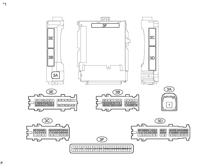
Text in Illustration *1 Instrument Panel Junction Block
-
Remove the main body ECU.
-
Measure the voltage and resistance of the wire harness side connectors.
Terminal No. (Symbol) Wiring Color Terminal Description Condition Specified Condition 3F-11 (GND1) - Body ground - Ground Always Below 1 Ω 3F-29 (ACC)*1 - Body ground - Ignition power supply
(ACC signal)
Ignition switch ACC → off 11 to 14 V → Below 1 V 3F-30 (BECU) - Body ground - +B (power system signal system) power supply Always 11 to 14 V 3F-32 (IG)*1 - Body ground - Ignition power supply (IG signal) Ignition switch ON → off 11 to 14 V → Below 1 V *1: w/o Smart Entry and Start System
If the result is not as specified, there may be a malfunction in the wire harness.
-
Reinstall the main body ECU.
-
Measure the voltage of the wire harness side connectors.
Terminal No. (Symbol) Wiring Color Terminal Description Condition Specified Condition 3E-35 (FRCY) - Body ground B - Body ground Driver side door courtesy light switch signal Driver side door closed → open
Ignition switch ON
Tongue plate fastened
Pulse generation → Below 1 V 3C-27 (LIN2) - Body ground P - Body ground LIN communication line Ignition switch ON Pulse generation 3C-28 (LIN2) - Body ground L*1 - Body ground LIN communication line Ignition switch ON Pulse generation Y*2 - Body ground
-
*1: for LHD
-
*2: for RHD
If the result is not as specified, there may be a malfunction on the wire harness.
-
-