ROOF HEADLINING INSTALLATION

-
INSTALL ANTENNA CORD SUB-ASSEMBLY
Note
-
Apply the tape securely in place.
-
Do not touch the adhesive surface when applying the tape to prevent adhesion failure.
-
Align the marking tapes on the antenna cord with the markings on the roof headlining.
-
Install the antenna cord onto the roof headlining with 2 new pieces of tape.
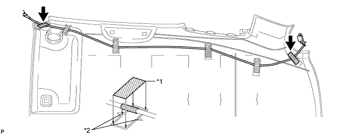
Text in Illustration: *1 Tape *2 Marking -
Align the antenna cord with the markings on the roof headlining with 3 new pieces of tape.
Text in Illustration *1 Tape *2 Marking -
Text in Illustration *1 Tape *2 Marking Install the rest of antenna cord onto the roof headlining with a new piece of tape.
-
-
INSTALL ROOF HEADLINING PAD
Text in Illustration *1 Mark
-
Align the 2 roof headlining pads with the marks on the roof headlining and install them onto the roof headlining.
-
-
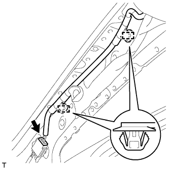
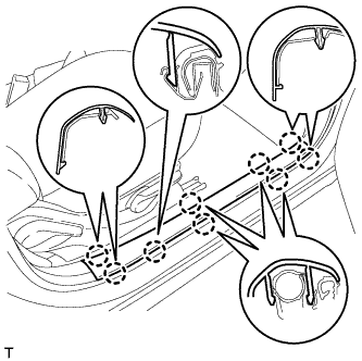
INSTALL ROOF WIRE
-
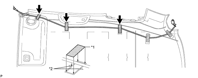
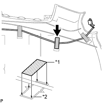
Align the 5 slit marks on the roof wire with the marks on the roof headlining, as shown in the illustration.
-
Align the joiner box for the roof wire with the marks on the roof headlining.
-
Install the roof wire onto the roof headlining with 7 new pieces of tape.
Note
-
Apply the tape securely in place.
-
Do not touch the adhesive surface when applying the tape to prevent adhesion failure.
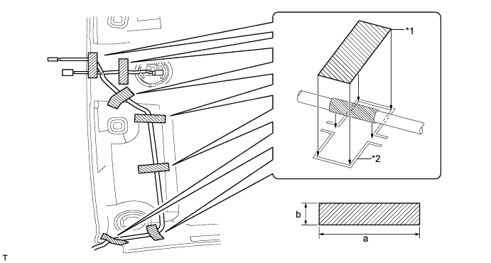
Text in Illustration *1 Tape *2 Marking Tape Size Area Dimension a 80 mm (3.15 in.) b 20 mm (0.79 in.) -
-
-
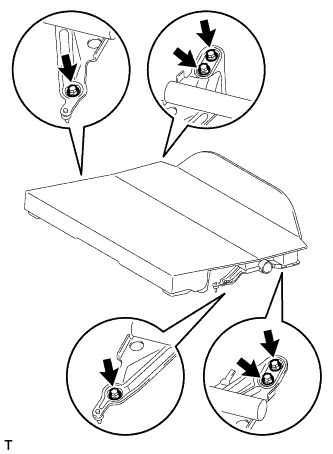
INSTALL NO. 1 ROOF SILENCER PAD
-
Install the 3 double-sided tapes.
-
Align the 3 No. 1 roof silencer pads with the markings on the roof headlining and install them onto the roof headlining.
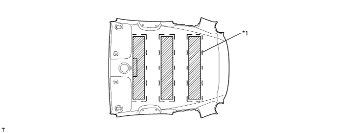
Text in Illustration *1 Marking
-
-
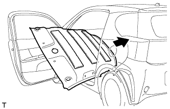
INSTALL ROOF HEADLINING
-
Pull the roof headlining back into the vehicle through the front door.
-
Install the 2 clips.
-
Install the bracket with the bolt.
-
Connect the 2 connectors.
-
-
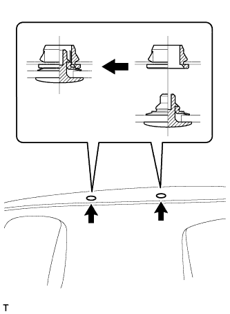
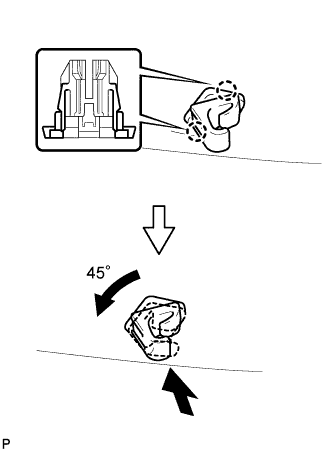
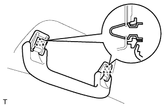
INSTALL VISOR HOLDER
Tech Tips
Use the same procedure as for the RH side.
-
Engage the 2 claws.
-
Push in the visor holder and turn it approximately 45° as shown in the illustration.
-
-
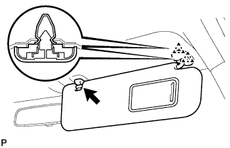
INSTALL VISOR ASSEMBLY RH
-
Engage the 2 clips and install the visor.
-
Install the visor shaft into the visor holder.
-
Engage the 4 claws and install a new visor cover.
-
-
INSTALL VISOR ASSEMBLY LH
Tech Tips
Use the same procedure as for the RH side.
-
INSTALL ASSIST GRIP
Tech Tips
Use the same procedure to install all assist grips.
-
Engage the 2 clips and install the assist grip.
-
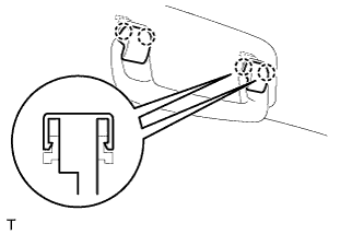
Engage the 4 claws and install the 2 assist grip covers.
-
-
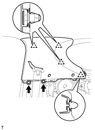
INSTALL FRONT PILLAR GARNISH RH (w/ Curtain Shield Airbag)
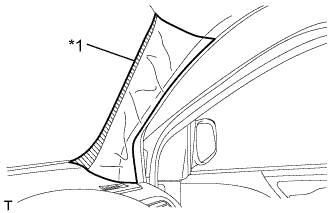
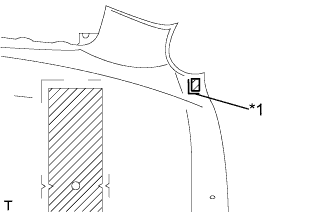
Text in Illustration *1 Protective Cover
-
Remove the protective cover.
-
Engage the 2 clamps.
-
Connect the connector.
-
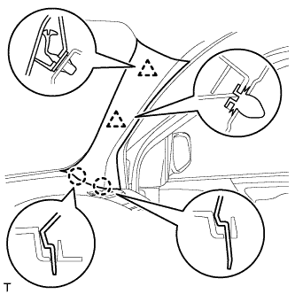
Install a new front pillar garnish clip onto the front pillar garnish.
-
Engage the 2 clips and 2 claws and install the front pillar garnish.
-
-
INSTALL FRONT PILLAR GARNISH RH (w/o Curtain Shield Airbag)
-
Engage the 2 clamps.
-
Connect the connector.
-
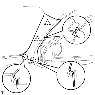
Engage the 2 clips and the 2 claws and install the front pillar garnish.
-
-
INSTALL FRONT PILLAR GARNISH LH
Tech Tips
Use the same procedure as for the RH side.
-
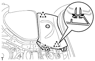
INSTALL RAIN SENSOR
-
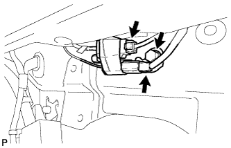
INSTALL INNER REAR VIEW MIRROR ASSEMBLY (w/ EC Mirror)
-
Connect the connector.
-
Engage the 4 claws and install the inner rear view mirror stay holder cover A.
-
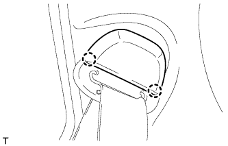
Slide the inner rear view mirror in the direction indicated by the arrow in the illustration to install it.
-
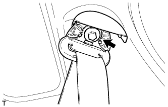
Using a T20 "TORX" socket wrench, install the screw.
- Torque:
- 1.5 N*m { 15 kgf*cm, 13 in.*lbf }
-
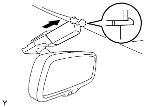
Slide the inner rear view mirror stay holder cover B in the direction indicated by the arrow to engage the 2 claws and install the inner rear view mirror stay holder cover B.
-
-
INSTALL INNER REAR VIEW MIRROR ASSEMBLY (w/o EC Mirror)
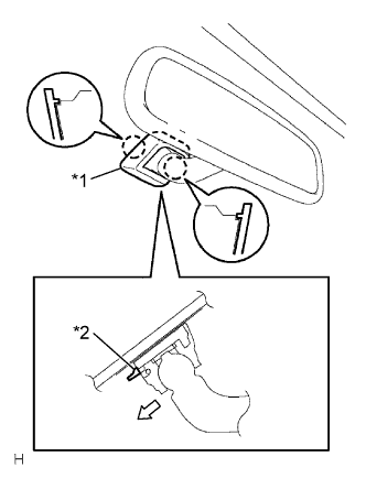
Text in Illustration *1 Cover *2 Claw
-
Install the inner rear view mirror as shown in the illustration.
-
Install the cover.
-
-
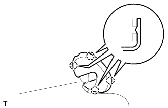
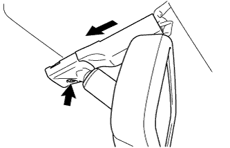
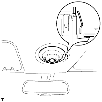
INSTALL PERSONAL LIGHT ASSEMBLY
-
Connect the connector.
-
Engage the claw and install the personal light.
-
-
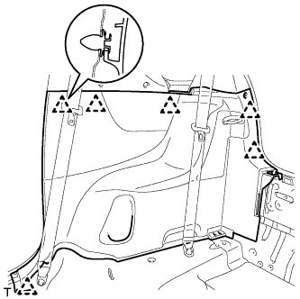
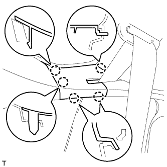
INSTALL ROOF SIDE INNER GARNISH RH
-
Engage the 3 clips and install the roof side inner garnish.
-
-
INSTALL ROOF SIDE INNER GARNISH LH
Tech Tips
Use the same procedure as for the RH side.
-
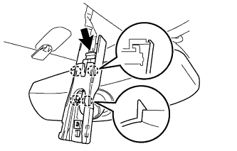
INSTALL REAR SEAT OUTER BELT ASSEMBLY RH
-
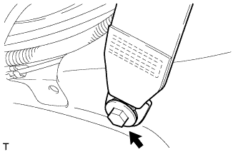
Install the rear seat outer belt with the bolt.
- Torque:
- 41 N*m { 420 kgf*cm, 30 ft.*lbf }
-
Engage the 2 claws and install the rear seat belt anchor cover.
-
-
INSTALL REAR SEAT OUTER BELT ASSEMBLY LH
Tech Tips
Use the same procedure as for the RH side.
-
INSTALL CENTER PILLAR UPPER GARNISH RH
-
Install 3 new clips to the center pillar upper garnish.
-
Engage the 4 clips and install the center pillar upper garnish.
-
Install the 2 clips.
-
-
INSTALL CENTER PILLAR UPPER GARNISH LH
Tech Tips
Use the same procedure as for the RH side.
-
INSTALL FRONT SEAT OUTER BELT ASSEMBLY RH
-
Install the front seat outer belt with the bolt.
- Torque:
- 41 N*m { 420 kgf*cm, 30 ft.*lbf }
-
-
INSTALL FRONT SEAT OUTER BELT ASSEMBLY LH
Tech Tips
Use the same procedure as for the RH side.
-
INSTALL SIDE NO. 1 TRIM ASSEMBLY RH
-
Engage the 6 clips and install the side No. 1 trim.
-
-
INSTALL SIDE NO. 1 TRIM ASSEMBLY LH
Tech Tips
Use the same procedure as for the RH side.
-
INSTALL DECK TRIM SIDE BELT HOLE COVER RH
-
Engage the 5 claws and install the deck trim side belt hole cover.
-
-
INSTALL DECK TRIM SIDE BELT HOLE COVER LH
Tech Tips
Use the same procedure as for the RH side.
-
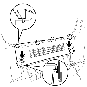
INSTALL REAR DECK TRIM COVER
-
Engage the 6 claws.
-
Install the rear deck trim cover with the 2 clips.
-
-
INSTALL FRONT DOOR OPENING TRIM WEATHERSTRIP RH
-
INSTALL FRONT DOOR OPENING TRIM WEATHERSTRIP LH
-
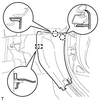
INSTALL COWL SIDE TRIM BOARD RH
-
Engage the guide and 2 claws and install the cowl side trim board.
-
-
INSTALL COWL SIDE TRIM BOARD LH
Tech Tips
Use the same procedure as for the RH side.
-
INSTALL FRONT DOOR SCUFF PLATE RH
-
Engage the 9 claws and install the front door scuff plate.
-
-
INSTALL FRONT DOOR SCUFF PLATE LH
Tech Tips
Use the same procedure as for the RH side.
-
INSTALL REAR SEAT ASSEMBLY
-
INSTALL REAR FLOOR BOARD SUB-ASSEMBLY (w/o Rear Seat)
-
Install the rear floor board with the 6 bolts.
- Torque:
- 37 N*m { 377 kgf*cm, 27 ft.*lbf }
-
-
CONNECT CABLE TO NEGATIVE BATTERY TERMINAL
- Torque:
- 5.4 N*m { 55 kgf*cm, 48 in.*lbf }
-
INSPECT SRS WARNING LIGHT