HEATER EXHAUST PIPE INSTALLATION

-
INSTALL EXHAUST PIPE
-
Install the exhaust pipe with the 2 nuts.
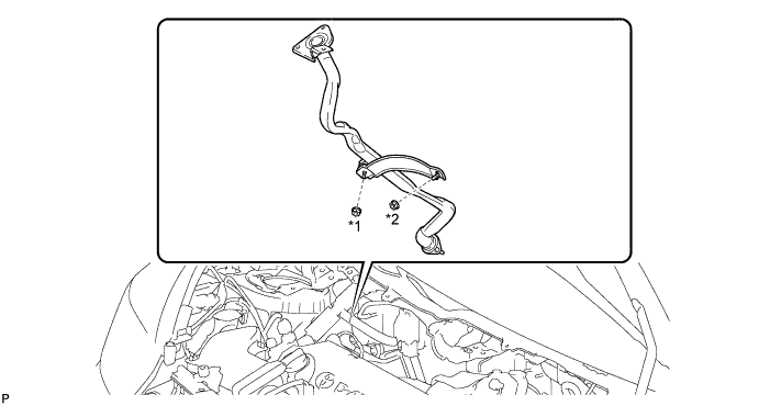
- Torque:
- 5.4 N*m { 55 kgf*cm, 48 in.*lbf, for nut *1 }
- Torque:
- 7.5 N*m { 76 kgf*cm, 66 in.*lbf, for nut *2 }
-
-
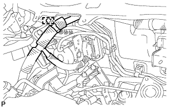
CONNECT ENGINE ROOM MAIN WIRE
-
Engage the clamp and connect the engine room main wire.
-
-
INSTALL TIE ROD END SUB-ASSEMBLY RH
-
Use the same procedure as for the LH side Click here.
-
-
INSTALL OIL LEVEL DIPSTICK GUIDE
-
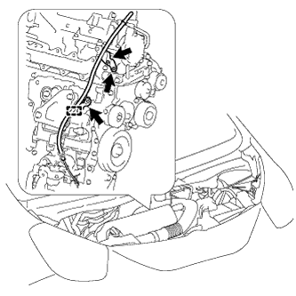
Install the O-ring to the oil level dipstick guide.
-
Install the oil level dipstick guide with the 2 bolts.
- Torque:
- 9.0 N*m { 92 kgf*cm, 80 in.*lbf }
-
Engage the harness clamp and install the oil level dipstick guide and wire harness with the bolt.
- Torque:
- 9.0 N*m { 92 kgf*cm, 80 in.*lbf }
-
-
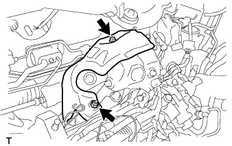
INSTALL MANIFOLD SUPPORT BRACKET
-
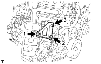
Temporarily tighten the manifold support bracket with the 2 bolts and nut.
-
Fully tighten the 2 bolts and nut, as shown in the illustration.
- Torque:
- 37 N*m { 377 kgf*cm, 27 ft.*lbf }
-
-
INSTALL NO. 2 TURBO INSULATOR
-
Install the No. 2 turbo insulator with the bolt and nut.
- Torque:
- 7.0 N*m { 71 kgf*cm, 62 ft.*lbf }
-
-
INSTALL HEATER AND ACCESSORY ASSEMBLY
-
Install the heater and accessory assembly Click here.
-