HEATER ASSEMBLY INSTALLATION

-
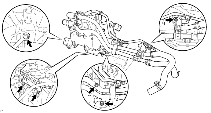
INSTALL HEATER AND ACCESSORY ASSEMBLY
-
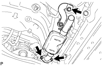
Set the heater and accessory assembly into the vehicle.
-
Tighten the 2 bolts and connect the heater exhaust pipe.
- Torque:
- 5.4 N*m { 55 kgf*cm, 48 in.*lbf }
-
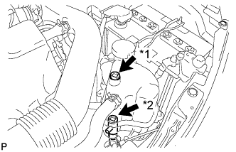
Install the heater and accessory assembly with the 4 nuts.
- Torque:
- 7.5 N*m { 76 kgf*cm, 66 in.*lbf, for nut*1 }
- Torque:
- 5.4 N*m { 55 kgf*cm, 48 in.*lbf, for nut*2 }
-
-
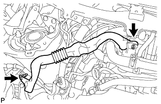
INSTALL AIR DUCT
-
Install the air duct with the 2 clips.
-
-
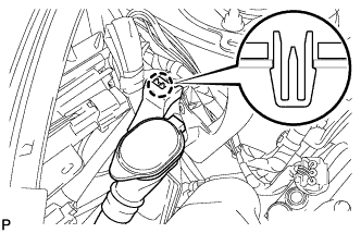
INSTALL WINDSHIELD WASHER JAR ASSEMBLY
-
Engage the claw and install the windshield washer jar.
-
-
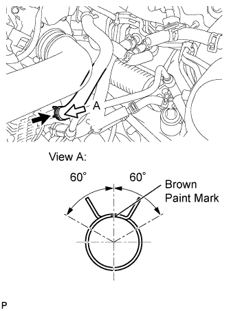
CONNECT HEATER WATER INLET HOSE E
-
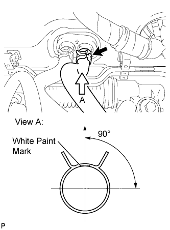
Install the heater water inlet hose onto the engine assembly.
Tech Tips
Perform the installation with the hose clip and mark at the correct angle.
-
-
CONNECT HEATER WATER OUTLET HOSE
-
Install the heater water outlet hose onto the heater unit.
Tech Tips
Perform the installation with the hose clip and mark at the correct angle.
-
-
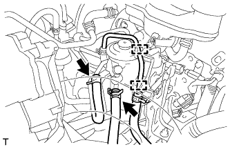
INSTALL NO. 1 HOSE TO HOSE TUBE
-
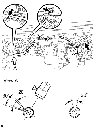
Install the hose to hose tube with the 2 bolts.
- Torque:
- 7.8 N*m { 80 kgf*cm, 69 in.*lbf }
-
Install the hose to hose tube onto the vacuum pump and brake booster.
Tech Tips
Perform the installation with the hose clip and mark at the correct angle.
-
-
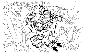
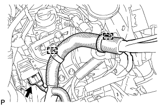
INSTALL HEATER PUMP ASSEMBLY
-
Install the heater pump with the nut.
- Torque:
- 7.5 N*m { 76 kgf*cm, 66 in.*lbf }
-
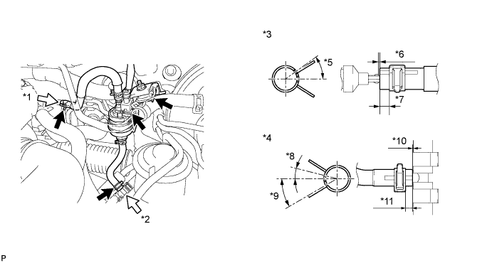
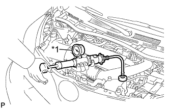
Install the fuel hose onto the fuel tube.
*1 A *7 2 to 7 mm (0.079 to 0.276 mm) *2 B *8 10° *3 View A *9 30° *4 View B *10 -3 to 0 mm (-0.118 to 0 mm) *5 30° *11 2 to 6 mm (0.079 to 0.236 mm) *6 -3 to 0 mm (-0.118 to 0 mm) - Tech Tips
Perform the installation with the hose clip and mark at the correct angle.
-
-
INSTALL FUEL FILTER ASSEMBLY
-
Install the fuel filter with the 2 nuts.
- Torque:
- 19 N*m { 189 kgf*cm, 14 ft.*lbf }
-
Connect the 2 fuel hose clamps to the fuel filter.
-
Connect the 2 fuel hoses to the fuel filter.
-
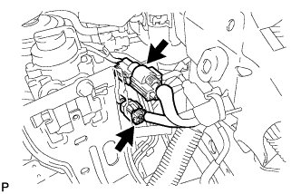
Connect the 2 connectors.
-
Connect the 2 wire harness clamps.
-
Connect the connector.
-
-
INSTALL BATTERY TRAY
-
INSTALL BATTERY
-
INSTALL BATTERY CLAMP SUB-ASSEMBLY
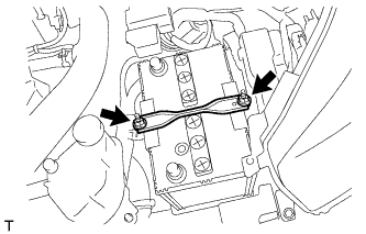
-
Install the battery clamp with the 2 nuts.
- Torque:
- 3.5 N*m { 36 kgf*cm, 31 in.*lbf }
-
-
INSTALL EXHAUST PIPE SUB-ASSEMBLY
-
Install the bolt and 2 nuts.
- Torque:
- 7.5 N*m { 76 kgf*cm, 66 in.*lbf }
-
-
INSTALL TAIL EXHAUST PIPE ASSEMBLY
-
Install the tail exhaust pipe assembly Click here.
-
-
INSTALL WINDSHIELD WIPER MOTOR AND LINK ASSEMBLY
-
Install the windshield wiper motor and link assembly Click here.
-
-
ADD ENGINE COOLANT
-
Tighten the radiator drain cock plug.
-
Text in Illustration *1 Air Bleed Valve 1 *2 Air Bleed Valve 2 Loosen the air bleed valve 1 and the air bleed valve 2.
-
Add TOYOTA Super Long Life Coolant (SLLC).
Standard Capacity Item Capacity w/ Combustion Type Power Heater 4.9 liters (5.2 US qts, 4.3 Imp. qts) Note
Never use water as a substitute for engine coolant.
Tech Tips
TOYOTA vehicles are filled with TOYOTA SLLC at the factory. In order to avoid damage to the engine cooling system and other technical problems, only use TOYOTA SLLC or similar high quality ethylene glycol based non-silicate, non-amine, non-nitrite, non-borate coolant with long-life hybrid organic acid technology (coolant with long-life hybrid organic acid technology is a combination of low phosphates and organic acids).
-
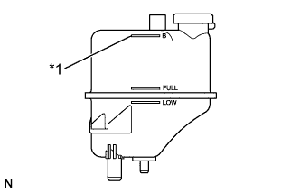
Text in Illustration *1 B Line Add coolant to B line of the radiator reserve tank.
-
Squeeze the inlet and outlet radiator hoses several times by hand, and then check the level of the coolant.
If the coolant level is low, add coolant.
-
Text in Illustration *1 Air Bleed Valve 1 *2 Air Bleed Valve 2 Tighten the air bleed valve 1 and the air bleed valve 2.
-
Start the engine, maintain the speed at 3000 rpm for 10 seconds, and idle the engine for 10 seconds. Repeat the same procedure above 4 more times.
-
Install the reserve tank cap sub-assembly.
-
Loosen the air bleed valve 1 and the air bleed valve 2.
-
Add 350 cc (21.3 cu in.) coolant.
-
Tighten the air bleed valve 1 and the air bleed valve 2.
-
Start the engine and warm it up.
-
Bleed air from the cooling system.
Note
-
Before starting the engine, turn the A/C switch off.
-
Adjust the air conditioning temperature setting to MAX (HOT).
-
Adjust the air conditioning blower setting to LO.
-
Warm up the engine until the thermostat opens. While the thermostat is open, allow the coolant to circulate for several minutes.
Tech Tips
Thermostat opening timing can be determined by squeezing the inlet radiator hose, and sensing vibrations when the engine coolant starts to flow inside the hose.
CAUTION:
When squeezing the radiator hoses:
-
Wear protective gloves.
-
Be careful as the radiator hoses are hot.
-
Keep your hands away from the radiator fan.
-
-
-
Stop the engine, and wait until the engine coolant cools down.
-
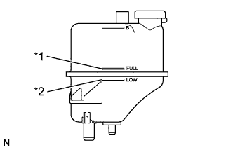
Text in Illustration *1 FULL Line *2 LOW Line After the engine has cooled down, check that the coolant level is between the FULL and LOW lines.
If the coolant level is low, add coolant to the reservoir tank FULL line.
-
-
INSPECT FOR COOLANT LEAK
CAUTION:
To avoid the danger of being burned, do not remove the radiator cap sub-assembly while the engine and radiator assembly are still hot. Thermal expansion will cause hot engine coolant and steam to blow out from the radiator assembly.
-
Text in Illustration *1 Radiator Cap Tester Fill the radiator assembly with engine coolant, and attach a radiator cap tester.
-
Pump the tester to 118 kPa (1.2 kgf/cm2, 17.1 psi), and then check that the pressure does not drop.
If the pressure drops, check the hoses, radiator assembly and water pump assembly for leaks. If there are no signs or traces of external engine coolant leaks, check the heater core, cylinder block and head.
-
-
INSPECT FOR FUEL LEAK
-
Connect an intelligent tester to the DLC3.
-
Turn the ignition switch to ON.
-
Turn the tester on.
-
Enter the following menus: Powertrain / Engine / Active Test.
-
Perform the Active Test.
Intelligent Tester Display Test Details Control Range Diagnostic Notes Test the Fuel Leak Pressurize common rail internal fuel pressure, and check for fuel leaks Stop/Start Perform inspection of the high pressure fuel system.
Test is possible when the following conditions are met:
-
Warmed up engine.
-
Vehicle is stopped.
-
Battery voltage is 12 V or more.
-
PM regeneration is not operating.
-
Engine speed is less than 4000 rpm.
Results of real-vehicle check:
-
Engine Speed: 2702 rpm
-
Fuel Pressure: 108570 kPa
-
Target Common Rail Pressure: 105500 kPa
-
Target Pump SCV Current: 1.2 A
-
MAP: 127 kPa
-
MAF: 28 g/sec.
-
-
-
BLEED AIR FROM FUEL SYSTEM
Tech Tips
Bleed air from fuel system Click here.
-
WARM UP ENGINE
Note
Warm up the engine at less than 2000 rpm for 1 minute or more after charging it with refrigerant.
-
INSPECT FOR EXHAUST GAS LEAK