INSTRUMENT PANEL SAFETY PAD INSTALLATION

-
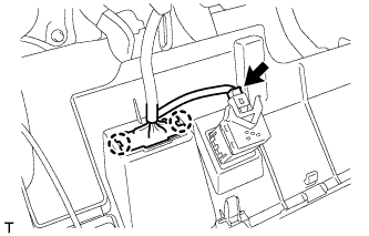
INSTALL PUSH START SWITCH
-
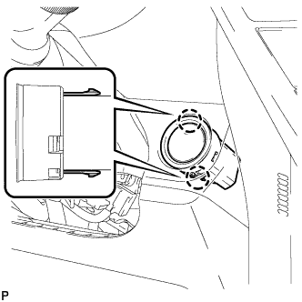
Engage the 2 claws to install the engine switch.
-
Connect the engine switch connector.
-
-
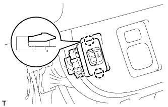
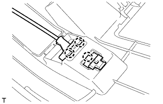
INSTALL HEADLIGHT LEVELING SWITCH
-
Engage the 2 claws and install the headlight leveling switch.
-
Connect the connector.
-
-
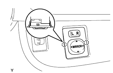
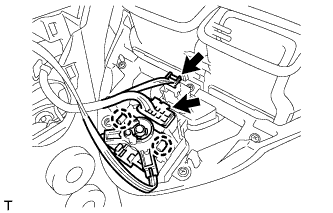
INSTALL OUTER MIRROR SWITCH ASSEMBLY
-
Engage the 2 claws and install the outer mirror switch.
-
Connect the connector.
-
-
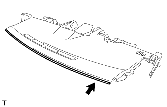
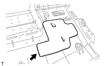
INSTALL INSTRUMENT PANEL CUSHION
-
Install the instrument panel cushion onto the instrument panel.
-
-
INSTALL NO. 1 INSTRUMENT PANEL CUSHION
-
Install the No. 1 instrument panel cushion onto the instrument panel.
-
Engage the 3 claws.
-
-
INSTALL NO. 2 INSTRUMENT PANEL CUSHION
-
Install the No. 2 instrument panel cushion onto the instrument panel.
-
-
INSTALL NO. 1 HEATER TO REGISTER DUCT SUB-ASSEMBLY
-
Install the No. 1 heater to register duct with the <A> screw.
-
-
INSTALL NO. 2 HEATER TO REGISTER DUCT SUB-ASSEMBLY
-
Install the No. 2 heater to register duct with the 5 <A> screws.
-
-
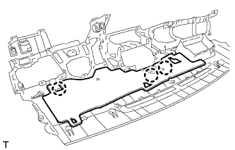
INSTALL NO. 2 ANTENNA CORD SUB-ASSEMBLY
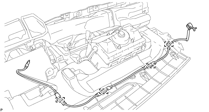
-
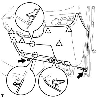
Engage the 4 clamps and install the No. 2 antenna cord.
-
-
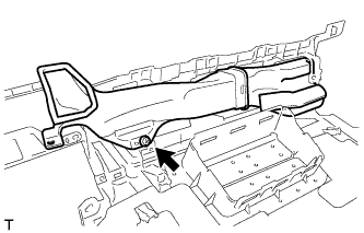
INSTALL NO. 2 SIDE DEFROSTER NOZZLE DUCT
-
Install the No. 2 side defroster nozzle duct with the 2 <A> screws.
-
-
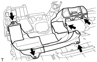
INSTALL DEFROSTER NOZZLE ASSEMBLY
-
Install the defroster nozzle with the 3 <A> screws.
-
Engage the clamp.
-
-
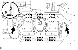
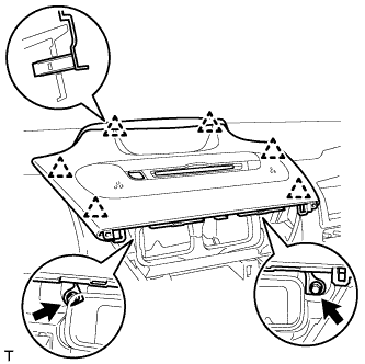
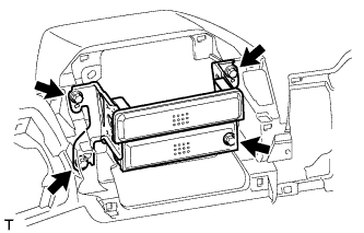
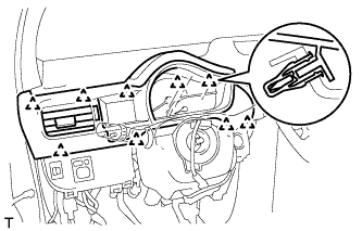
INSTALL INSTRUMENT PANEL PASSENGER AIR BAG ASSEMBLY
-
Engage the 6 hooks so that the connector side faces the outside of the vehicle, and install the front passenger airbag.
-
Install the 2 screws.
-
Install the wire harness onto the claw of the instrument panel.
-
-
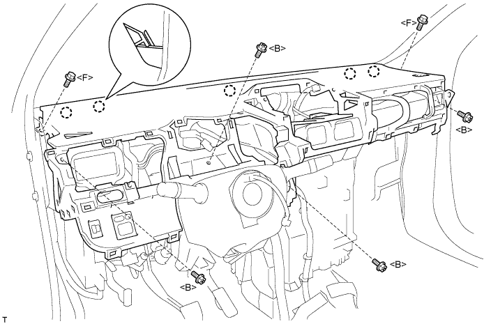
INSTALL INSTRUMENT PANEL SUB-ASSEMBLY
-
Engage the 5 claws.
-
Install the instrument panel with the 2 <F> bolts and 4 <B> screws.
-
Install the instrument panel passenger air bag with the 2 < G> bolts.
- Torque:
- 20 N*m { 204 kgf*cm, 15 ft.*lbf }
-
Connect the all connectors.
-
-
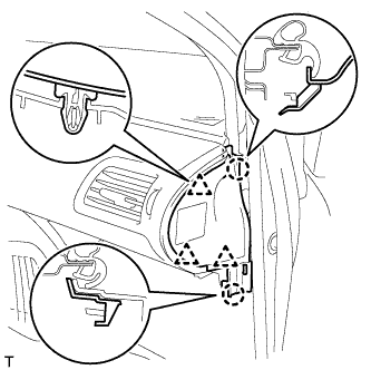
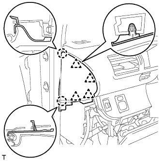
INSTALL FRONT PILLAR GARNISH RH (w/ Curtain Shield Airbag)
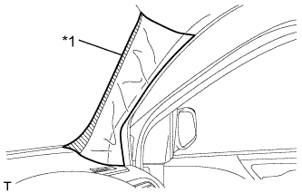
Text in Illustration *1 Protective Cover
-
Remove the protective cover.
-
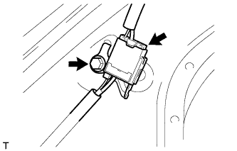
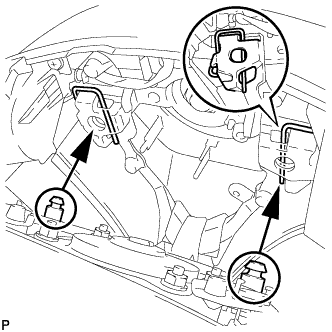
Install the antenna cord with the bolt.
-
Connect the connector.
-
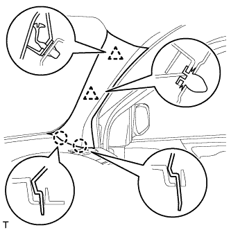
Install a new front pillar garnish clip onto the front pillar garnish.
-
Engage the 2 clips and 2 claws and install the front pillar garnish.
-
-
INSTALL FRONT PILLAR GARNISH RH (w/o Curtain Shield Airbag)
-
Install the antenna cord with the bolt.
-
Connect the connector.
-
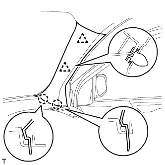
Engage the 2 clips and the 2 claws and install the front pillar garnish.
-
-
INSTALL FRONT PILLAR GARNISH LH
Tech Tips
Use the same procedure as for the RH side.
-
INSTALL LOWER INSTRUMENT PANEL
-
Engage the 2 claws and 4 clips.
-
Install the lower instrument panel with the 3 <F> bolts and <E> screw.
-
-
INSTALL UPPER INSTRUMENT PANEL SUB-ASSEMBLY
-
Engage the 6 clips.
-
Install the upper instrument panel with the <F> bolt.
-
-
INSTALL INSTRUMENT SIDE PANEL LH
-
Engage the 2 claws and 3 clips and install the instrument side panel LH.
-
-
INSTALL LOWER NO. 2 INSTRUMENT PANEL FINISH PANEL
-
Engage the 4 claws and 2 clips.
-
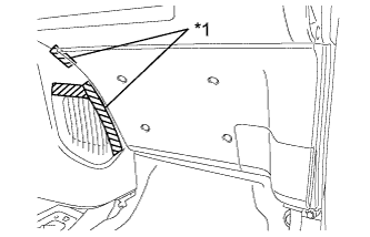
Text in Illustration *1 Protective Tape Remove the protective tape.
-
Install the lower No. 2 instrument panel with the <C> bolt.
-
-
INSTALL CENTER NO. 1 INSTRUMENT CLUSTER FINISH PANEL (w/ Audio)
-
Connect the all connectors.
-
Engage the 6 clips.
-
Install the center No. 1 instrument cluster finish panel with the 2 bolts.
-
-
INSTALL STEREO OPENING COVER (w/o Audio)
-
Install the stereo opening cover with the 4 bolts.
-
-
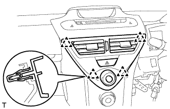
INSTALL CENTER NO. 1 INSTRUMENT CLUSTER FINISH PANEL (w/o Audio)
-
w/ Arrow Mark
-
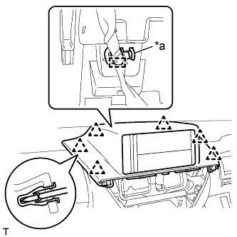
Text in Illustration *a Arrow Mark Engage the clamp.
Note
To avoid damaging the clamp, do not rotate it during installation.
-
Connect the connector.
-
Engage the 6 clips and install the center No. 1 instrument cluster finish panel.
-
-
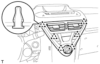
w/o Arrow Mark
-
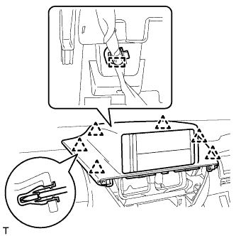
Engage the clamp.
-
Connect the connector.
-
Engage the 6 clips and install the center No. 1 instrument cluster finish panel.
-
-
-
INSTALL LOWER CENTER INSTRUMENT CLUSTER FINISH PANEL SUB-ASSEMBLY (for Manual Air Conditioning System)
-
Connect all the connectors.
-
Engage the 2 claws and connect the air mix damper control cable.
-
Engage the 2 claws and connect the No. 2 heater control cable.
-
Engage the 8 clips and install the lower center instrument cluster finish panel.
-
-
INSTALL LOWER CENTER INSTRUMENT CLUSTER FINISH PANEL SUB-ASSEMBLY (for Automatic Air Conditioning System)
-
Connect the connector.
-
Engage the 8 clips and install the lower center instrument cluster finish panel.
-
-
INSTALL FRONT CONSOLE BOX COVER
-
Engage the 2 claws and 4 clips and install the front console box cover.
-
-
INSTALL CENTER LOWER INSTRUMENT CLUSTER FINISH PANEL (for Manual Air Conditioning System)
-
Connect the all connectors.
-
Engage the 2 claws and connect the air inlet damper control cable.
-
Engage the 4 clips and install the center lower instrument cluster finish panel.
-
-
INSTALL INSTRUMENT CLUSTER FINISH PANEL ASSEMBLY (for Automatic Air Conditioning System)
-
Connect the connector.
-
Engage the 6 clips and install the instrument cluster finish panel.
-
-
INSTALL COMBINATION METER ASSEMBLY
-
Connect the 2 connectors.
-
Engage the 2 clips.
-
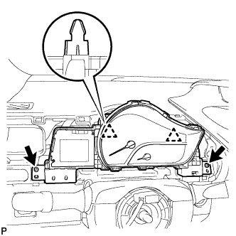
Install the combination meter with 2 screws.
-
-
INSTALL INSTRUMENT CLUSTER FINISH NO. 1 PANEL
-
Engage the 9 clips and install the instrument cluster finish No. 1 panel.
-
-
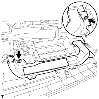
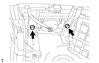
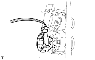
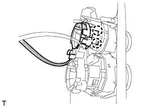
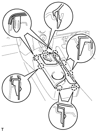
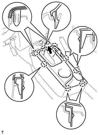
INSTALL REAR CONSOLE BOX ASSEMBLY

-
Engage the 2 front clips.
-
Rotate the 2 rear clips in the direction indicated by the arrows to engage them and install the console box assembly RR.
-
-
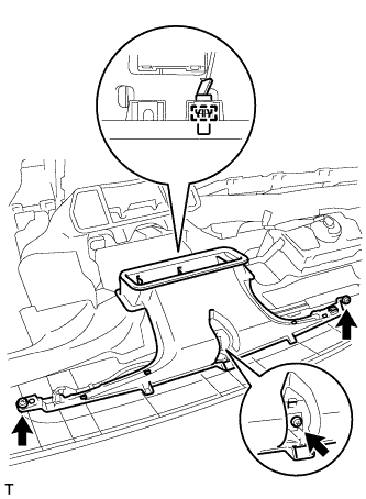
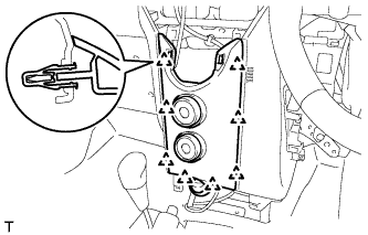
INSTALL CONSOLE UPPER PANEL SUB-ASSEMBLY (for CVT)
-
Engage the 8 claws and install the console upper panel.
-
-
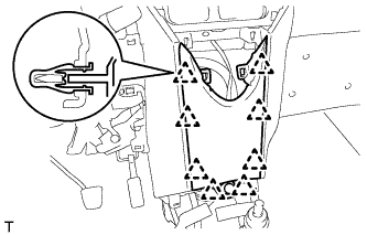
INSTALL CONSOLE UPPER PANEL SUB-ASSEMBLY (for Manual Transaxle)
-
Install the shifting hole cover onto the shift lever.
-
Engage the 8 claws and install the console upper panel.
-
-
INSTALL SHIFT LEVER KNOB SUB-ASSEMBLY (for Manual Transaxle)
-
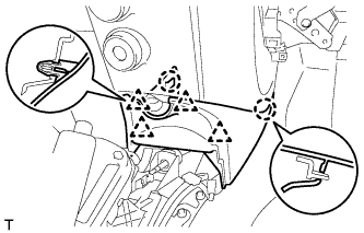
INSTALL LOWER NO. 1 INSTRUMENT PANEL AIR BAG ASSEMBLY
-
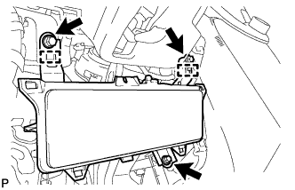
Engage the 2 guides and install the knee airbag assembly.
-
Install the 3 bolts.
- Torque:
- 10 N*m { 102 kgf*cm, 7 ft.*lbf }
-
-
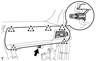
INSTALL INSTRUMENT SIDE PANEL RH
-
Engage the 2 claws and 4 clips and install the instrument side panel RH.
-
-
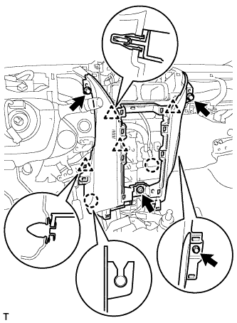
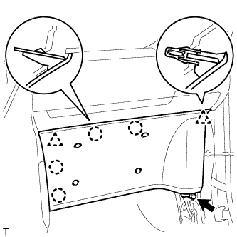
INSTALL LOWER NO. 1 INSTRUMENT PANEL FINISH PANEL (for LHD)
-
Engage the 3 claws and connect the hood lock control lever.
-
Connect the connector.
-
Engage the 2 claws and connect the DLC3 connector.
-
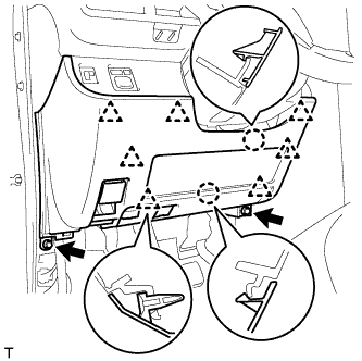
Engage the 2 claws and 7 clips.
-
Install the lower No. 1 instrument panel finish panel with the 2 <C> bolts.
-
-
INSTALL LOWER NO. 1 INSTRUMENT PANEL FINISH PANEL (for RHD)
-
Engage the 3 claws and connect the hood lock control lever.
-
Connect the connector.
-
Engage the 2 claws and connect the DLC3 connector.
-
Engage the 2 claws and 8 clips.
-
Install the lower No. 1 instrument panel finish panel with the 2 <C> bolts.
-
-
INSTALL FRONT DOOR OPENING TRIM WEATHERSTRIP RH
-
INSTALL FRONT DOOR OPENING TRIM WEATHERSTRIP LH
-
INSTALL COWL SIDE TRIM BOARD RH
-
Engage the guide and the 2 claws and install the cowl side trim board.
-
-
INSTALL COWL SIDE TRIM BOARD LH
Tech Tips
Use the same procedure as for the RH side.
-
INSTALL FRONT DOOR SCUFF PLATE RH
-
Engage the 9 claws and install the front door scuff plate.
-
-
INSTALL FRONT DOOR SCUFF PLATE LH
Tech Tips
Use the same procedure as for the RH side.
-
INSTALL STEERING WHEEL ASSEMBLY
-
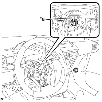
Text in Illustration *a Matchmark Align the matchmarks and install the steering wheel assembly onto the steering column assembly.
-
Install the nut.
- Torque:
- 50 N*m { 510 kgf*cm, 37 ft.*lbf }
-
Connect all the connectors to the spiral cable.
-
-
INSTALL STEERING PAD
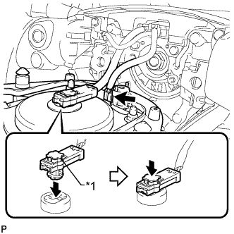
Note
Do not use a steering pad that has been dropped.
Text in Illustration *1 Locking Button
-
Confirm that the ignition switch is off.
-
Confirm that the cable to the negative battery terminal is disconnected.
CAUTION:
Wait at least 90 seconds after disconnecting the cable from the negative (-) battery terminal to disable the SRS system.
-
Connect the horn terminal.
-
Connect the airbag connector.
Note
-
Match the color of the airbag connector with that of the steering pad assembly, and install the airbag connector.
-
Securely lock the locking button.
-
-
Engage the pins into the spring clips behind the horn button assembly to install the steering pad.
Note
Pull the horn button assembly to ensure that it is securely engaged.
Tech Tips
Install the right-side pin of the horn button assembly first.
-
-
CONNECT CABLE TO NEGATIVE BATTERY TERMINAL
- Torque:
- 5.4 N*m { 55 kgf*cm, 48 in.*lbf }
-
INSPECT SRS WARNING LIGHT