LIGHTING SYSTEM Hazard Warning Switch Circuit
DESCRIPTION
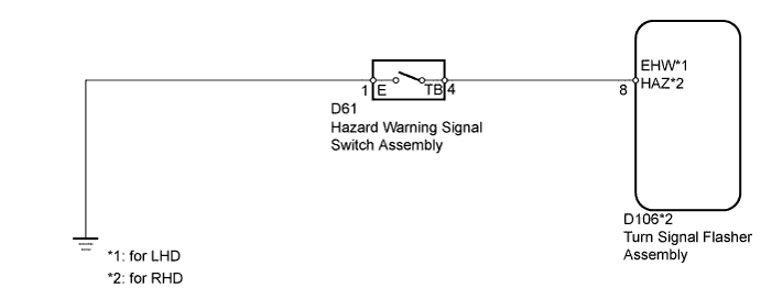
The turn signal flasher receives a hazard warning signal switch information signal, and illuminates the turn signal lights.
WIRING DIAGRAM
INSPECTION PROCEDURE
PROCEDURE
-
INSPECT HAZARD WARNING SIGNAL SWITCH ASSEMBLY
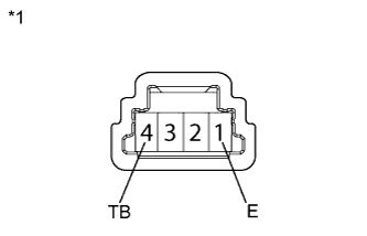
Text in Illustration *1 Component without harness connected
(Hazard Warning Signal Switch Assembly)
-
Remove the hazard warning signal switch Click here.
-
Measure the resistance according to the value(s) in the table below.
Standard Resistance Tester Connection Switch Condition Specified Condition 1 (E) - 4 (TB) Hazard warning signal switch on Below 1 Ω Hazard warning signal switch off 10 kΩ or higher
NG 
REPLACE HAZARD WARNING SIGNAL SWITCH ASSEMBLY Click here
OK 
-
-
CHECK HARNESS AND CONNECTOR (HAZARD WARNING SIGNAL SWITCH - TURN SIGNAL FLASHER AND BODY GROUND)
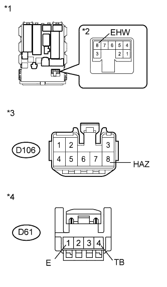
Text in Illustration *1 Component without harness connected
(Main Body ECU [for LHD])
*2 Component without harness connected
(Center Airbag Sensor)
*3 Front view of wire harness connector
(to Turn Signal Flasher Assembly [for RHD])
*4 Front view of wire harness connector
(to Hazard Warning Signal Switch Assembly)
-
Disconnect the D61 hazard warning signal switch connector.
-
for LHD:
Remove the turn signal flasher.
-
for RHD:
Disconnect the D106 turn signal flasher connector.
-
Measure the resistance according to the value(s) in the table below.
Standard Resistance for LHD Tester Connection Condition Specified Condition D61-4 (TB) - 8 (EHW) Always Below 1 Ω D61-1 (E) - Body ground Always Below 1 Ω D61-4 (TB) - Body ground Always 10 kΩ or higher for RHD Tester Connection Condition Specified Condition D61-4 (TB) - D106-8 (HAZ) Always Below 1 Ω D61-1 (E) - Body ground Always Below 1 Ω D61-4 (TB) - Body ground Always 10 kΩ or higher
NG
REPAIR OR REPLACE HARNESS OR CONNECTOR
OK 
PROCEED TO NEXT SUSPECTED AREA SHOWN IN PROBLEM SYMPTOMS TABLE Click here
-