LIGHTING SYSTEM Turn Signal Light Circuit
DESCRIPTION
The turn signal flasher receives a turn signal switch signal from the headlight dimmer switch, and illuminates the front turn signal light, side turn signal light and rear combination light.
WIRING DIAGRAM

INSPECTION PROCEDURE
Tech Tips
Inspect the fuses and bulbs for circuits related to this system before performing the following inspection procedure.
PROCEDURE
-
CHECK TURN SIGNAL LIGHT
-
Check the operation of the turn signal lights.
Result Result Proceed to All turn signal lights do not blink A Front turn signal light does not blink B Rear combination light does not blink C Side turn signal light does not blink D
B 
CHECK HARNESS AND CONNECTOR (FRONT TURN SIGNAL LIGHT - TURN SIGNAL FLASHER AND BODY GROUND) Click here
C
CHECK HARNESS AND CONNECTOR (REAR COMBINATION LIGHT - TURN SIGNAL FLASHER AND BODY GROUND) Click here
D
INSPECT OUTER REAR VIEW MIRROR ASSEMBLY Click here
A 
-
-
CHECK HARNESS AND CONNECTOR (TURN SIGNAL FLASHER - BATTERY, IGNITION SWITCH AND BODY GROUND)
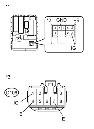
Text in Illustration *1 Component without harness connected
(Main Body ECU [for LHD])
*2 Turn Signal Flasher Assembly *3 (to Turn Signal Flasher Assembly [for RHD])
-
for LHD:
Remove the turn signal flasher.
-
for RHD:
Disconnect the D106 turn signal flasher connector.
-
Measure the voltage according to the value(s) in the table below.
Standard Voltage for LHD Tester Connection Switch Condition Specified Condition 1 (IG) - Body ground Ignition switch ON 11 to 14 V Ignition switch off Below 1 V 4 (+B) - Body ground Always 11 to 14 V for RHD Tester Connection Switch Condition Specified Condition D106-1 (IG) - Body ground Ignition switch ON 11 to 14 V Ignition switch off Below 1 V D106-4 (B) - Body ground Always 11 to 14 V -
Measure the resistance according to the value(s) in the table below.
Standard Resistance for LHD Tester Connection Condition Specified Condition 7 (GND) - Body ground Always Below 1 Ω for RHD Tester Connection Condition Specified Condition D106-7 (E) - Body ground Always Below 1 Ω
NG 
REPAIR OR REPLACE HARNESS OR CONNECTOR
OK 
PROCEED TO NEXT SUSPECTED AREA SHOWN IN PROBLEM SYMPTOMS TABLE Click here
-
-
CHECK HARNESS AND CONNECTOR (FRONT TURN SIGNAL LIGHT - TURN SIGNAL FLASHER AND BODY GROUND)
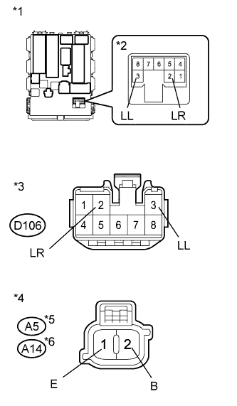
Text in Illustration *1 Component without harness connected
(Main Body ECU [for LHD])
*2 Turn Signal Flasher Assembly *3 Front view of wire harness connector
(to Turn Signal Flasher Assembly [for RHD])
*4 Front view of wire harness connector
(to Front Turn Signal Light)
*5 for LH *6 for RH
-
for LH:
-
Disconnect the A5 front turn signal light connector.
-
for LHD:
Remove the turn signal flasher.
-
for RHD:
Disconnect the D106 turn signal flasher connector.
-
Measure the resistance according to the value(s) in the table below.
Standard Resistance for LHD Tester Connection Condition Specified Condition A5-2 (B) - 3 (LL) Always Below 1 Ω A5-1 (E) - Body ground Always Below 1 Ω A5-2 (B) - Body ground Always 10 kΩ or higher for RHD Tester Connection Condition Specified Condition A5-2 (B) - D106-3 (LL) Always Below 1 Ω A5-1 (E) - Body ground Always Below 1 Ω A5-2 (B) - Body ground Always 10 kΩ or higher
-
-
for RH:
-
Disconnect the A14 front turn signal light connector.
-
for LHD:
Remove the turn signal flasher.
-
for RHD:
Disconnect the D106 turn signal flasher connector.
-
Measure the resistance according to the value(s) in the table below.
Standard Resistance for LHD Tester Connection Condition Specified Condition A14-2 (B) - 2 (LR) Always Below 1 Ω A14-1 (E) - Body ground Always Below 1 Ω A14-2 (B) - Body ground Always 10 kΩ or higher for RHD Tester Connection Condition Specified Condition A14-2 (B) - D106-2 (LR) Always Below 1 Ω A14-1 (E) - Body ground Always Below 1 Ω A14-2 (B) - Body ground Always 10 kΩ or higher
-
NG
REPAIR OR REPLACE HARNESS OR CONNECTOR
OK
PROCEED TO NEXT SUSPECTED AREA SHOWN IN PROBLEM SYMPTOMS TABLE Click here
-
-
CHECK HARNESS AND CONNECTOR (REAR COMBINATION LIGHT - TURN SIGNAL FLASHER AND BODY GROUND)
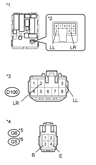
Text in Illustration *1 Component without harness connected
(Main Body ECU [for LHD])
*2 Turn Signal Flasher Assembly *3 (to Turn Signal Flasher Assembly [for RHD]) *4 Front view of wire harness connector
(to Rear Combination Light Assembly)
*5 for LH *6 for RH
-
for LH:
-
Disconnect the G6 rear combination light connector.
-
for LHD:
Remove the turn signal flasher.
-
for RHD:
Disconnect the D106 turn signal flasher connector.
-
Measure the resistance according to the value(s) in the table below.
Standard Resistance for LHD Tester Connection Condition Specified Condition G6-3 (B) - 3 (LL) Always Below 1 Ω G6-4 (E) - Body ground Always Below 1 Ω G6-3 (B) - Body ground Always 10 kΩ or higher for RHD Tester Connection Condition Specified Condition G6-3 (B) - D106-3 (LL) Always Below 1 Ω G6-4 (E) - Body ground Always Below 1 Ω G6-3 (B) - Body ground Always 10 kΩ or higher
-
-
for RH:
-
Disconnect the G5 rear combination light connector.
-
for LHD:
Remove the turn signal flasher.
-
for RHD:
Disconnect the D106 turn signal flasher connector.
-
Measure the resistance according to the value(s) in the table below.
Standard Resistance for LHD Tester Connection Condition Specified Condition G5-3 (B) - 2 (LR) Always Below 1 Ω G5-4 (E) - Body ground Always Below 1 Ω G5-4 (B) - Body ground Always 10 kΩ or higher for RHD Tester Connection Condition Specified Condition G5-3 (B) - D106-2 (LR) Always Below 1 Ω G5-4 (E) - Body ground Always Below 1 Ω G5-4 (B) - Body ground Always 10 kΩ or higher
-
NG
REPAIR OR REPLACE HARNESS OR CONNECTOR
OK
PROCEED TO NEXT SUSPECTED AREA SHOWN IN PROBLEM SYMPTOMS TABLE Click here
-
-
INSPECT OUTER REAR VIEW MIRROR ASSEMBLY
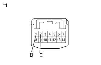
Text in Illustration *1 Component without wire harness connected
(Outer Rear View Mirror Assembly)
-
Remove the outer rear view mirror Click here.
-
Apply battery voltage to the terminals and check that the side turn signal light turns on.
OK Tester Connection Specified Condition Battery positive (+) → 1 (B)
Battery negative (-) → 2 (E)
Side turn signal light turns on
NG
CHECK SIDE TURN SIGNAL LIGHT ASSEMBLY Click here
OK
-
-
CHECK HARNESS AND CONNECTOR (OUTER REAR VIEW MIRROR - TURN SIGNAL FLASHER AND BODY GROUND)
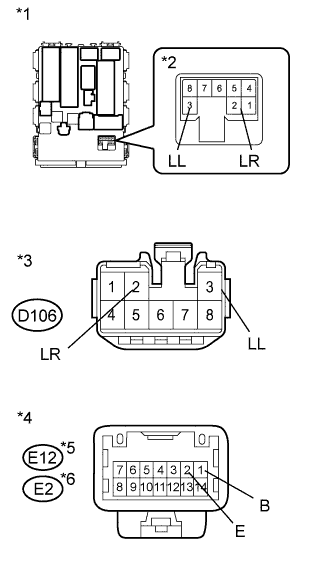
Text in Illustration *1 Component without harness connected
(Main Body ECU [for LHD])
*2 Turn Signal Flasher Assembly *3 Front view of wire harness connector
(to Turn Signal Flasher Assembly [for RHD])
*4 Front view of wire harness connector
(to Outer Rear View Mirror Assembly)
*5 for LH *6 for RH
-
for LH:
-
Disconnect the E12 outer rear view mirror connector.
-
for LHD:
Remove the turn signal flasher.
-
for RHD:
Disconnect the D106 turn signal flasher connector.
-
Measure the resistance according to the value(s) in the table below.
Standard Resistance for LHD Tester Connection Condition Specified Condition E12-1 (B) - 3 (LL) Always Below 1 Ω E12-2 (E) - Body ground Always Below 1 Ω E12-1 (B) - Body ground Always 10 kΩ or higher for RHD Tester Connection Condition Specified Condition E12-1 (B) - D106-3 (LL) Always Below 1 Ω E12-2 (E) - Body ground Always Below 1 Ω E12-1 (B) - Body ground Always 10 kΩ or higher
-
-
for RH:
-
Disconnect the E2 outer rear view mirror connector.
-
for LHD:
Remove the turn signal flasher.
-
for RHD:
Disconnect the D106 turn signal flasher connector.
-
Measure the resistance according to the value(s) in the table below.
Standard Resistance for LHD Tester Connection Condition Specified Condition E2-1 (B) - 2 (LR) Always Below 1 Ω E2-2 (E) - Body ground Always Below 1 Ω E2-1 (B) - Body ground Always 10 kΩ or higher for RHD Tester Connection Condition Specified Condition E2-1 (B) - D106-2 (LR) Always Below 1 Ω E2-2 (E) - Body ground Always Below 1 Ω E2-1 (B) - Body ground Always 10 kΩ or higher
-
NG
REPAIR OR REPLACE HARNESS OR CONNECTOR
OK
PROCEED TO NEXT SUSPECTED AREA SHOWN IN PROBLEM SYMPTOMS TABLE Click here
-
-
CHECK SIDE TURN SIGNAL LIGHT ASSEMBLY
-
Temporarily replace the side turn signal light with a new or normally functioning one Click here.
-
Check that the side turn signal light blinks.
OK Side turn signal light blinks.
NG
REPLACE OUTER REAR VIEW MIRROR ASSEMBLY Click here
OK
END (SIDE TURN SIGNAL LIGHT ASSEMBLY IS DEFECTIVE)
-