BACK DOOR REASSEMBLY

-
INSTALL BACK DOOR STAY BOLT (for LH Side)
-
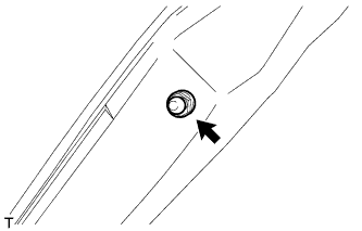
When replacing the back door stay bolt with a new one:
-
Clean the threaded portion on the vehicle body with a non-residue solvent.
-
Install the back door stay bolt.
- Torque:
- 22 N*m { 224 kgf*cm, 16 ft.*lbf }
-
-
When reusing the back door stay bolt:
-
Clean the threaded portion on the vehicle body with a non-residue solvent.
-
Apply adhesive to the threads of the back door stay bolt.
Adhesive Toyota Genuine Adhesive 1324, Three Bond 1324 or equivalent -
Install the back door stay bolt.
- Torque:
- 22 N*m { 224 kgf*cm, 16 ft.*lbf }
-
-
-
INSTALL BACK DOOR STAY BOLT (for RH Side)
Tech Tips
Use the same procedure described for the LH side.
-
INSTALL UPPER BACK DOOR DAMPER STAY BRACKET LH
-
Clean the threaded portion on the vehicle body with a non-residue solvent.
-
Apply adhesive to the threads of the 2 bolts.
Adhesive Toyota Genuine Adhesive 1324, Three Bond 1324 or equivalent -
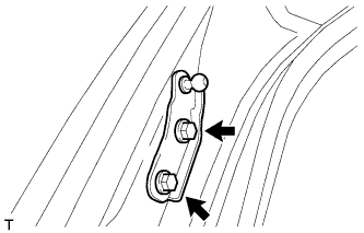
Install the upper back door damper stay bracket with the 2 bolts.
- Torque:
- 7.0 N*m { 71 kgf*cm, 62 in.*lbf }
-
-
INSTALL UPPER BACK DOOR DAMPER STAY BRACKET RH
Tech Tips
Use the same procedure described for the LH side.
-
INSTALL BACK DOOR STAY ASSEMBLY LH
-
Install the 2 stop rings to the back door stay assembly.
-
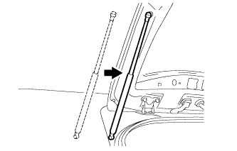
Install the back door stay assembly.
Note
Install the back door stay assembly while supporting the back door by hand.
-
Check that the back door stay assembly is attached at the ball joint and that the back door stay assembly cannot be pulled off.
-
-
INSTALL BACK DOOR STAY ASSEMBLY RH
Tech Tips
Use the same procedure described for the LH side.
-
INSTALL REAR TELEVISION CAMERA ASSEMBLY (w/ Rear View Monitor System)
-
Attach the 2 claws to install the rear television camera assembly.
-
Connect the connector.
-
-
INSTALL BACK DOOR OPENER SWITCH ASSEMBLY
-
Connect the connector and install the back door opener switch.
-
-
INSTALL LICENSE PLATE LIGHT ASSEMBLY
-
Attach the 4 claws to install the 2 lights.
-
Connect the 2 connectors.
-
-
INSTALL BACK DOOR GARNISH SUB-ASSEMBLY OUTSIDE
-
Attach the clip to install the back door outside garnish.
-
Install the back door outside garnish with the 5 nuts.
- Torque:
- 5.0 N*m { 51 kgf*cm, 44 in.*lbf }
-
-
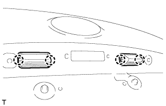
INSTALL REAR LIGHT LENS AND BODY LH
-
Install the rear light lens and body LH with the 4 nuts.
-
Connect the connector.
-
-
INSTALL REAR LIGHT LENS AND BODY RH
Tech Tips
Use the same procedure described for the LH side.
-
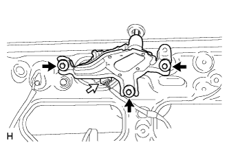
INSTALL BACK DOOR LOCK ASSEMBLY
Note
-
When installing a new back door lock assembly, if there is any tape stuck to it, remove the tape.
-
When installing a new back door lock assembly, if there are any strings attached to it, cut the strings off.
-
Connect the connector.
-
Install the back door lock assembly with the 3 bolts.
- Torque:
- 13 N*m { 133 kgf*cm, 10 ft.*lbf }
-
-
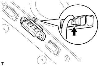
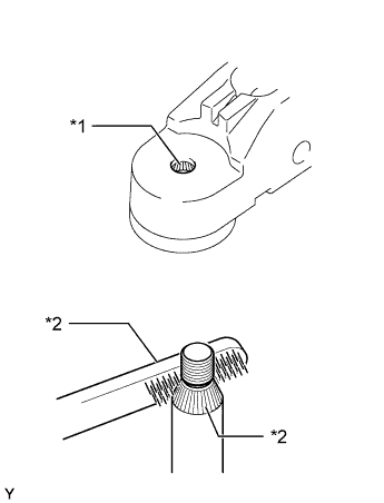
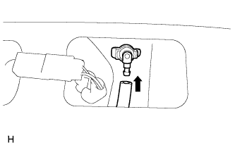
INSTALL REAR WIPER MOTOR GROMMET
-
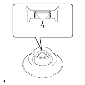
Text in Illustration *1 MP grease Apply MP grease to the entire surface of the wiper motor grommet lip.
Tech Tips
Make sure that the hole does not get clogged with grease and the grooves on the lip are filled with grease.
-
Text in Illustration *1 Position Mark Install the rear wiper motor grommet with the position mark facing upward as shown in the illustration.
-
-
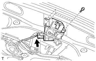
INSTALL REAR WIPER MOTOR ASSEMBLY
-
Temporarily install the rear wiper motor assembly with the 3 bolts.
-
Tighten the 3 bolts.
- Torque:
- 5.5 N*m { 56 kgf*cm, 49 in.*lbf }
-
Connect the connector.
-
-
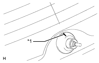
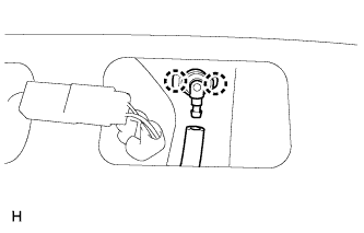
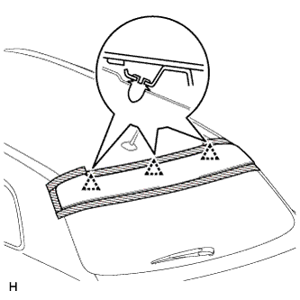
INSTALL REAR WIPER ARM
-
Operate the rear wiper, and stop the rear wiper motor at the automatic stop position.
-
Text in Illustration *1 Wiper Arm Pivot Serrations *2 Wire Brush *3 Wiper Pivot Serrations Clean the serrations with a wire brush.
-
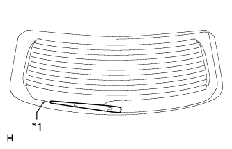
Text in Illustration *1 Defogger Line Set the head of the blade on the defogger line.
-
Install the rear wiper arm with the nut.
- Torque:
- 5.5 N*m { 56 kgf*cm, 49 in.*lbf }
-
Close the wiper arm head cap.
-
-
INSTALL REAR WASHER NOZZLE
-
Attach the 2 claws to install the washer nozzle.
-
Connect the hose.
-
-
INSTALL CENTER STOP LIGHT ASSEMBLY
-
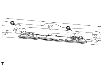
Connect the connector.
-
Install the stop light with the 2 screws.
-
-
INSTALL REAR SPOILER
-
Pass the wire harness through the back door panel.
-
Attach the 3 clips to install the rear spoiler.
-
Text in Illustration *1 Grommet Install the 4 nuts and 2 grommets.
-
Connect the connector and clamp.
-
-
INSTALL DOOR PULL HANDLE
-
Attach the 4 claws to install the door pull handle.
Tech Tips
Use the same procedure for all door pull handles.
-
-
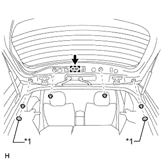
INSTALL BACK DOOR TRIM BOARD ASSEMBLY
-
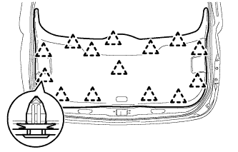
Attach the 14 clips to install the back door trim board.
-
-
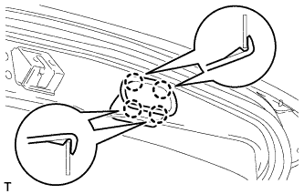
INSTALL BACK DOOR SIDE GARNISH LH
-
Attach the 2 clips and claw to install the back door side garnish.
-
-
INSTALL BACK DOOR SIDE GARNISH RH
-
Attach the 2 clips and claw to install the back door side garnish.
-
-
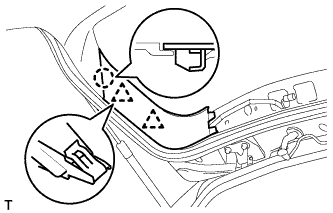
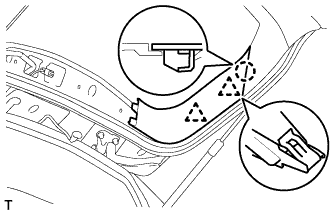
INSTALL UPPER BACK DOOR TRIM PANEL ASSEMBLY
-
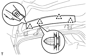
Attach the 4 clips to install the upper back door trim panel
-